40 cent magnetic angle sensing technique

Finally the time has come to try this again, and it works great! Better in every way from digital halls. Easier, cheaper, and more precise. Fewer wires and CPU pins needed, and can run on 3.3V.

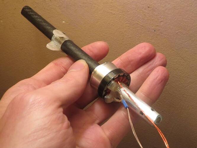
This time I’m using a 2204 motor which I’ve hacked up and glued to a gearbox, and didn’t do a great job of it so it’s a little wobbly. The sensor mount is 3D printed.

I’ve also ground the lip off the underside of the rotor to allow more flux leakage and get the sensors nearly touching the magnets. The radial placement has them just outside of the copper coils so hitting the coils wouldn’t be the limiting factor on how close I could get to the magnets.

This motor is nice because I can easily change the axial distance. After some testing, I’d say around 1mm is best. The greater the distance, the more sinusoidal the waveform becomes, but the resolution diminishes. This gives a resolution of around 100-130 ADC counts, whereas placing the sensors very close to the magnets gets up to around 200 counts, but the waveform becomes more trapezoidal with inverted peaks. I suspect smaller radial distance would improve that, and then maybe you could get a bit better resolution before running into the coils.


You can also see the signature of the wobble in my motor. The amplitude varies throughout the 7 electrical revolutions as the magnets get closer and farther from the sensors. But since atan2 doesn’t have a specific input range, it makes no difference to the angle reading.

It appears the green sensor is slightly closer to the magnets since it has higher amplitude than the blue one. It runs a little better if I use the range scaling from XieMaster’s implementation, but I would vote for nanoparticle’s version to be the one included in SimpleFOC for its speed and simplicity (only subtracting the center value for each sensor). Better to fix the amplitude issue by adjusting sensor distance.

There seems to be a problem with the ADC configuration using the Generic G031G8Ux configuration on Lepton, because it’s taking 250 microseconds per analogRead. My main loop is 400 micros otherwise, so the majority of the time is spent reading sensors. Low speed works fine but it tops out around 100rad/s.
5 Likes

So the ADC configuration turns out to be a major hurdle, and not something I can tackle myself due to lack of hardware to test all the different versions of it. It should be possible to configure for good performance on an individual basis, but it will be a while before this sensor class is usable out of the box, at least on STM32 (analogRead may be fast enough on other platforms).

Also, I was curious if you could replace the digital halls in a hoverboard motor with linear halls and use clarke transform to convert the 3 signals to an angle. But after testing with one sensor, it looks like the signal is too saturated to use.

Not sure if this helps, but you can get linear halls with varying sensitivity (I actually had the opposite problem and was looking for more sensitive halls for a project a while back). Check out the
HX6639 series of hall sensors, with the A, B, C, and D variants.

1 Like

I finally found the actual hardware documentation for Lepton’s STM32G031 https://www.st.com/en/microcontrollers-microprocessors/stm32g0-series/documentation.html and the ADC is really easy to use if you bypass the ridiculously overcomplicated HAL and LL libraries and just work with the registers directly. Seriously, what even is the point of a library if it makes it more difficult to figure out what is the proper sequence of operations to accomplish a task, while wasting massive amounts of CPU cycles and flash space, and is still different for each line of stm32 chips?

I’ve added a weakly bound function ReadLinearHalls that does the analogRead operations, so you can override it with custom code on platforms with bad analogRead implementation. The register #defines here are my own, so this code will not compile directly, but shows how little work actually needs to be done to operate the ADC.

void ReadLinearHalls(int pinA, int pinB, int *a, int *b)
{
  ADCISR = ADCISR_ADRDY | ADCISR_CCRDY; // Clear flags
  ADCCFGR1 = ADCCFGR1_WAIT; // Wait until ADCDR is read before starting second conversion
  ADCCFGR2 = ADCCFGR2_OVSE | ADCCFGR2_PVSR(3) | ADCCFGR2_OVSS(4); // 16x oversampling, shifted down 4 bits
  ADCCHSELR = (1<<pinA)|(1<<pinB);
  ADCCR |= ADCCR_ADEN; // Enable ADC
  while(!(ADCISR & ADCISR_ADRDY) && !(ADCISR & ADCISR_CCRDY));
  ADCCR |= ADCCR_ADSTART;
  while(!(ADCISR & ADCISR_EOC));
  sensor.lastA = ADCDR; // Reading ADCDR clears the end-of-conversion flag
  while(!(ADCISR & ADCISR_EOC));
  sensor.lastB = ADCDR;
  ADCCR |= ADCCR_ADDIS; // Disable ADC (saves power, and would need re-armed by next frame anyway (100us t-idle from datasheet)
}

Also a couple things needed in setup()

  RCCAPBENR2 |= RCCAPBENR2_ADCEN; // Enable ADC clock
  ADCCR = ADCCR_ADVREGEN; // Enable voltage regulator
  delayMicroseconds(20); // Voltage regulator startup time from STM32G031 datasheet

But when used together with hardware current sense, you will have to go through the HAL library and be careful not to step on the toes of the current sense ADC configuration.

The pinA and pinB variables refer to ADC channels in this case rather than port pin names like PA1, so I had to remove the pinMode(pin, INPUT); calls in LinearHall::init. But that should be fine since pins are typically input at startup, and in my case it’s convenient if nothing touches them because on STM32, digital input and analog input are separate modes, and analog is the default. You can always configure them manually before calling sensor.init if there are any platforms where it matters.

I’ve also got it going with the fast atan2 I linked in post #12. I’ve gone from over 700 microseconds for the angle reading (250 per analogRead, 200 for atan2) to 35 (7 for the ADC operations, 28 for atan2). About 2000% speedup :lol: And about 5kb of flash saved. And for the cost of 6 more microseconds I can have 8x oversampling to significantly improve the signal quality.

@nanoparticle If it’s ok with you, I’ll do a pull request with this in the main repository sensors folder, rather than drivers repository. Though I feel terrible replacing your name as the original contributor :frowning:

2 Likes

Absolutely go for it, especially since I’ve kind of moved on from this particular project. I really appreciate the effort, and definitely prefer to see progress be made.

2 Likes

Is this fast atan2 even faster than this one?

Apparently it’s been a while since I did a merge :slight_smile: That one measures about 43 micros, which makes sense due to having 9-10 flops instead of 6. Do you know what its maximum error is? I’m guessing it’s better than the 0.29 degrees for the one I’m using, since it has three constants instead of two.

I left in the comments the origin of this method:

To be honest, as I knew it was used in Odrive and MESC, I didn’t even try to understand how it works.

1 Like

Hey, guys. I was looking around foc drivers and I noticed this sin cos cordic method. Arduino-FOC-drivers/src/utilities/stm32math at dev · simplefoc/Arduino-FOC-drivers · GitHub
It needs specific stm32 proccesors that have the cordic hardware but it should be a lot less computationally intensive.

Neat, I didn’t know CORDIC did atan. It doesn’t look like it’s been implemented in that library you linked, but it is in the HAL headers. It would certainly be more accurate than the approximation functions we’ve been using, but since the sensor readings aren’t perfect sin/cos waves, I doubt the difference would be noticeable. It will need some testing to see how the speed compares.

Hi Swifty,

Welcome to SimpleFOC!

We already support the CORDIC for Sin/Cos on MCUs that have one:

For atan2 we’d have to switch it’s setup between Sine and Atan2 configuration each time between different operations, I think

1 Like