Thanks for sharing, circular position control would be amazing for any kind of vehicle.
1 Like
Hay,
How is the progress on next release?
@Antun_Skuric How can we use your version? Is it in a dev branch or anything?
Hey @Matt303, its in the separate branch for the moment: https://github.com/simplefoc/Arduino-FOC/tree/FEAT_velocity_feadforward
You can donwload it from there, but its not documented and there are no examples yet. Basically the only difference from the standard library is that it has motor.feed_forward_velocity variable which you can set in addition to the target value.
@Antun_Skuric do you use feedforward branch and the code posted above for the planner? What is the benefit feed forward velocity?
What is that slick GUI you’re using for tuning the parameters there? It doesn’t look like the SimpleFOCCommander I’ve seen elsewhere.
Edit: Aha, found it! Didn’t know about GitHub - simplefoc/simplefoc-webcontroller: Web controller for SimpleFOC using WebSerial at https://webcontroller.simplefoc.com/
1 Like
Yes, motion planning has been done before. What you are doing is planning in “joint space” and looking at accelerations of each jint independently. This is the simplest thing you can do. But it is not optimal.
For example, the first motor. How do you determine the maximum acceleration? That depends on (1) the mass of the payload in the gripper and (2) The distance between the payload and the first joint. The rotational inertia depends on the angle of the other joints. We all know that a weight in your hand is harder to move if you are holding the arm straight out away from your body. The weight is easier to move if you hold it close.
If you use a fixed trapezoid accelearion planner it will always have to assume the worst case and the robot will perform much poorer then it could
The trick is to do the planning in (X,Y,Z) space. You plan a 3D path thrugh space for the hand and then compute the joint angles and speeds needed to reach those points. The math is harder, so brush up on Linear Algebra. Basiclly what you need is a function that maps joint speed to tip-of-the-hand speed in three-space. There are now “cook book” solutions
That said, manual training and trapezoid accelleration will get the arm moving.
The best introduction is forward and reverse kinematics I have ever seen is an on-line course from a professor or mechanical engineering at Arizona State U. It is free (unless you want a grade and credit)
see this: https://robogrok.com.
Next if you are looking for a motion planner that handles colision avoidence with the environment and also avoids self colision and dose optimal planning look at “Move It”. But be warned, it is close to the state of the art and has a huge learning curve https://moveit.ros.org
The next step after you get this moving would be to work in forward and inverse kinematics, see robogrok for how to do that.
My current project is a robot quadruped. This is basically a box with for robot arms that serve as legs. Planning in joint space would be impossible, but not so bad in Cartesian space.
Looks like you have advanced past the initial question, but just fyi there are actually lot of systems that can do this for you from the CNC controller space. Like LinuxCNC is one but there are successors that are apparently better, I posted once on reddit if you can find the post you can see the discussion on the subject.
Basically you tell the system about the geometry of the robot and then you can tell it to move the effector to different cartesian coodinates and with different angles. Kinematics. They also handle acceleration etc. You tell it what to do with gcode. some support arms like this, some don’t. Look into successors to grbl too perhaps.
I know nothing bout ros etc. but it’s probably a better idea still if it’s more made for the purpose… The problem is you get a lot of projects that sound good but it turns out the details are rather hollow, a lot of bugs and stuff. I know linuxcnc is fairly solid.
LCNC would not work for a robot, unless it is the kind of robot that runs a pre-programmed script, like a CNC machine tool. Also the planner is only doing VERY short-term planning. In the CNC world the ltradjectory is worked out by the machinist or CAM software. The idea that the machine will make a bend around an arc is done I advance by a human. A robot planner needs to draw the arc itself. If it’s job is to pick up a part from a bin of loose, randomly oriented parts it needs to make the motion plan to align the gripper wit the object. A CNC machine works at a MUCH lower level.
Look at ROS MoveIt.
1 Like
For anyone interested in this topic, I have added a very simple trapezoidal planner to our SimpleFOC drivers repository:
The code is very simple, but quite effective at producing nice position profiles.
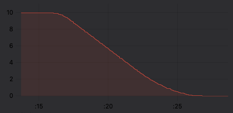
Velocity trapezoid (accelleration max: 1.0, decelleration max: 0.25, velocity max: 1.25):
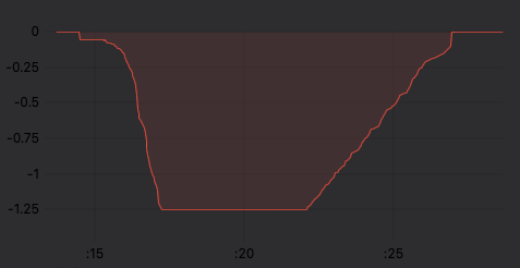
Position profile:
The code uses only the current position vs. the target position, and does not depend on reading the velocity or the time, which makes it quite stable.
Its a bit simple for many use cases probably, but the code is also so simple I thought it might be a nice starting point for people looking to implement higher level control on top of SimpleFOC.
7 Likes
Just checked out your code. This is really interesting. It’s wayyyy simpler than the trapezoidal code I posted at the start of this thread (many years ago). I’m kinda curious how it does its trick of being so simple and still achieving trapezoidal? Were you running into the more complex code operating too slowly on some microcontrollers, i.e. too slow of a control loop?
Actually no - I was kind of approaching the problem clean slate…
It’s based on the idea that the trapezoidal shape arises naturally from 3 limits: the acceleration limit, the maximum velocity and the deceleration limit (which could be the same as or different to the acceleration limit).
The maximum velocity is just a constant (horizontal line). The acceleration limit velocity (linearly ‘increasing’ line) can be expressed as a function purely of the distance from the starting point (my code is so simple it ignores the initial velocity, but this could be added easily enough). The deceleration limit (linearly ‘decreasing’ line) seems more complicated, but if you look at it “in reverse” and think of it as accelerating away from the destination, then its actually the same function as the acceleration, but just based on the distance to the target rather than from the starting point.
Velocity v(d) after accelerating at a constant acceleration A for a distance d is given by
v(d) = \sqrt{2Ad}
So given d_s from the starting point, and d_t to the target, acceleration A_a and deceleration A_d the limits are
lim_{accel} = \sqrt{2A_ad_s}
lim_{decel} = \sqrt{2A_dd_t}
lim_{vel} = v_{max}
The trapezoidal shape is the area between these limits and the 0-velocity axis, so it’s just a matter of taking the minimum value of the 3 limits.
I have to think about the real differences between your version and this simple one. I think this approach has a number of unaddressed issues, and I’m not sure it’s really a “planner” since you can’t directly control the speed of the motion - at the moment you’d have to do that indirectly by setting the right accel, max vel and decel values.
2 Likes