@runger DRV8316 looks very interesting.
Thanks for your suggestions.
@runger DRV8316 looks very interesting.
Thanks for your suggestions.
This chip also looks interesting. I wonder if STM32f0 or ESP32 can handle 3 of these?
https://www.st.com/resource/en/datasheet/vnh7100bas.pdf
Thanks
!!!
Awesome! ![]()
@Antun_Skuric Are there any gimbal motors on Amazon that you would recommend? I can’t find any of the ones mentioned in various project threads / in the supported hardware page, but if there’s an equivalent that’s not too far off in price from what’s currently being used, that would be an amazing help.
Edit: Likewise on the motor encoder. The only listing for the AMT103-V on Amazon is priced ridiculously high (~$220 USD) https://www.amazon.com/dp/B089ZFYYM4/
In the schematic above, I believe the bottom motor lead should go to out3 instead of out4 on the L298n.
Would this be similarly applicable to any dual output motor driver for normal DC motors? Like would the generic green MOSFET H-Bridge motor driver work for this by just using 3 of the 4 output pins?
Hi @jakabo27 ,
you have to be able to control their bridges seperately. The one you link has SPEED/DIR control, one (PWM) line for speed and one (digital high/low) line for direction. So you can’t control the bridges separately.
Also, the FETs are driven by a driver IC, which isn’t further documented on the product page, but which will often prevent the type of control you need to drive BLDCs - typically it won’t let you switch both high FETs on. Unfortunately, most of the cheap boards out there are “more advanced” than the L298N in this way, which makes them better for DC-motor control, but unsuitable for misuse as BLDC drivers.
However, poking around the associated products, this one might work for you. That’s not a recommendation, I haven’t tried it, but it seems it has no driver, just optoisolators, and individual control of the 4 FETs. So 3 of these should drive 2xBLDCs. I might try it out.
Hey @happytm - Maybe it will work with this chip. It does look like you can control the bridges separately. But it also has all kinds of protections, so hard to say. I doubt very much the current sensing it has will be useful for BLDC driving.
I don’t think it’s a good idea to use the L298 for anything serious. It is an old design based on bipolar transistors ( look at the huge losses in the power stage ) It’s intended use are 130 style toy motors like these : https://www.adafruit.com/product/711
Will this work will this work with tb6612?
For steppers yes, but for BLDCs not unfortunately.
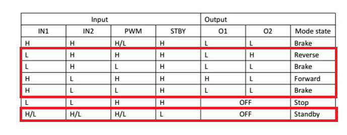
For example, in the datasheet they say that if both IN1 and IN2 inputs are LOW the OUT1 and OUT2 are open (high impedance).
One more driver to discuss among all of you experts:
Arduino library with examples:
Thanks.
Hey @happytm
I fear not - at least not for FOC control. While it looks good from the truth table and being able to control the two half-bridges separately, if you look at Table 4 there is a delay when switching the direction using INa/INb - a delay of 600-1800µs - this will be too much to use PWM on this pin.
Unfortunately this chip is designed to support PWM only on the PWM-pin, for speed control, but you can’t PWM the bridges seperately.
I see now. Thanks for your feedback.
Would the DRV8833 be usable for drone motors?
DRV8833 data sheet, product information and support | TI.com
Hey,
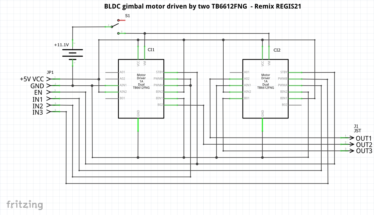
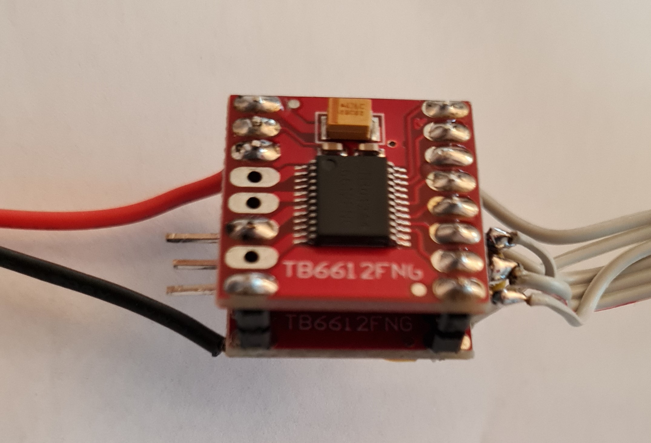
I was seeking for a small driver board for BLDC easy to integrate in my project. The Drotek L6234
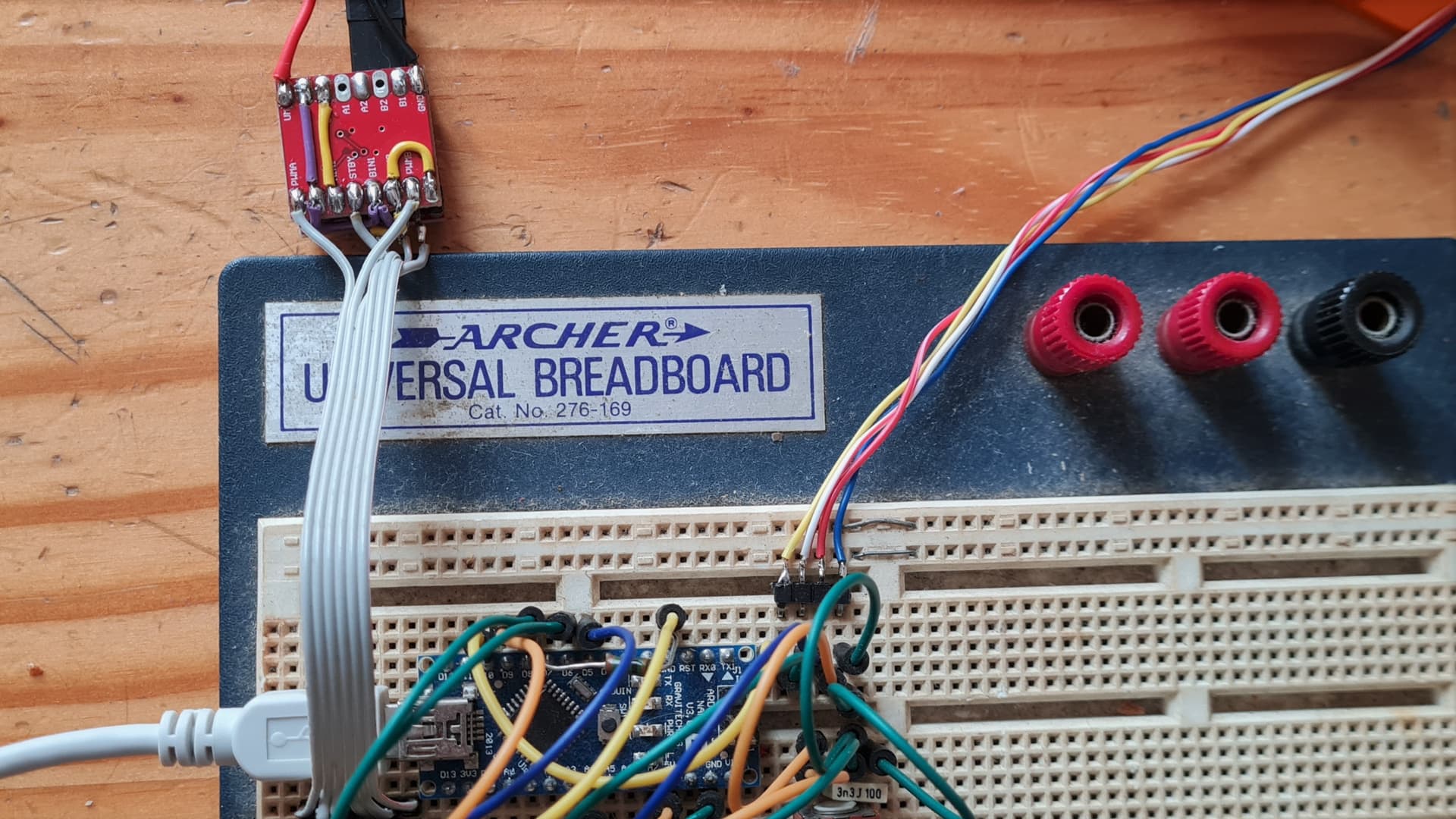
breakout board was welldone but sourcing looks hard. In the post was mentioned the tb6612 and I decided to test by implementing two of these stacked altogether and using the half of the H-bridge by output. This way no issue with high impedance logic. It was also mentioned in another post but apparently without success. The logic I followed is indicated in the table below and you will find the wiring too. Inputs are connected to the PWM and Enable to Standby. The IN1&2 are connected to the respective logic level. It requires pin header modifications and also bondings but with dimensions of 2x2x1.5cm it makes compact driver board. It is available for around 1€ by board on Chinese websites so it looks to me cheap solution compatible with a 3S Lipo for a current of 1.2A continuous and 3.2A peak. Looks to work well for me.
Hey @CREGIS21 , that’s a nice discovery! I will try this out when I get back home from vacation, I have a bunch of these boards lying around at home. This would indeed be a very cheap and small solution!
Very nice!
I was wondering if the same could be done with the drv8833 based chips. it seems to have the same issue.
but both of these chips seem like a good choice for stepper control. ![]()
This is interesting board for high power brush motors. It has dual H-Bridges with 24V 30A. Nice thing is it is Arduino uno hat.
More information for chip used and schematic design here - https://www.hobbytronics.co.uk/motor-control/motor-drivers/vnh5019-motor-driver
Can it be used with SimpleFOC?
Thanks.