3$ BLDC and Stepper FOC driver - L298N

Hi guys,

I just wanted to point out one interesting fact that I’ve found recently.
I bought the L298n breakout board from Amazon for under 3$ and have been using it to run stepper motors, namely nema17.

But I just realized that I can run a gimbal BLDC motors as well!
It has more or the less the same power ratting as the L6234 up to 4amps. I have not seen it being used or advertised in this context but it definitely should :smiley:

I am starting to think I should design a board around l298n with current sensing and make it a very interesting low-power motion control board. You could run:

  • Gimbal BLDC motor
  • Stepper motor
  • 2xDC motors

With two inline current sensors we could have a torque control for all of the motors.

But even without fancy (current sensing) shield, this board is everywhere and basically for 3$ you can run a SimpleFOClibrary for stepper of BLDC motor on it. I am impressed! :smiley:

6 Likes

Yes, low cost. This is good. But pcb dimensions are large. Much needed bldc breakout board similar to stepper motors A4988. I’m just talking about dimensions…

You can find the L298 in a nicer package:
image

its also a great driver for ultrasonic transducers:)

can you share the wiring setup and working code for this? I’d like to test it.

Connection example

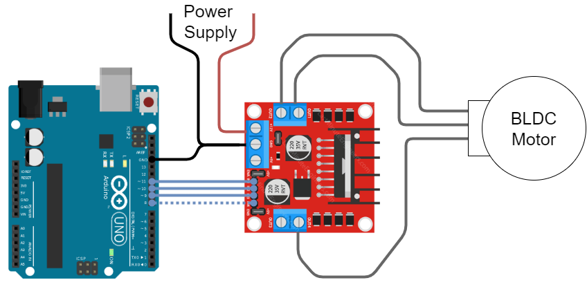
Here is the connection diagram.

  1. Connect the motor to the motor to the 3 out 4 outputs of the L298N
    Example:
    • OUT1 - motor phase A
    • OUT2 - motor phase B
    • OUT3 - motor phase C
  2. Connect the IN1,IN2,IN3 and IN4 to the Arduino. Make sure to connect the the INx ports with the same number as OUTx ports to the PWM pins. Example:
    • IN1 - 11
    • IN2 - 10
    • IN3 - 9
    • IN4 - 8 (doesn’t have to be pwm) - can be connected to GND directly
  3. Make sure that both ENA and ENB are HIGH.
    • On my board I have on both sides two pin jumper which does exactly this.
    • If you don’t have it, connect ENA and ENB to digital pins and set them to HIGH (or connect them to 5V pin directly)
  4. Connect the common ground of the MCU and L298N
  5. Connect the power supply
  6. Connect your sensor and everything else you will need for your FOC application - steps after step5. are no longer L298N specific.

Code Example

Now you can run any BLDCDriver3PWM example out there with this setup. Just make sure to either connect the IN4 to the ground directly or in the setup() function add:

pinMode(8,OUTPUT);
digitalWrite(8,LOW);

Here is the open loop example code:

// Open loop motor control example for L298N board
#include <SimpleFOC.h>

#define IN1 11
#define IN2 10
#define IN3 9
#define IN4 8

// BLDC motor & driver instance
// BLDCMotor motor = BLDCMotor(pole pair number);
BLDCMotor motor = BLDCMotor(11);
// BLDCDriver3PWM driver = BLDCDriver3PWM(pwmA, pwmB, pwmC, Enable(optional));
BLDCDriver3PWM driver = BLDCDriver3PWM(IN1, IN2, IN3);

void setup() {
  // deactivate the OUT4 output
  pinMode(IN4,OUTPUT);
  digitalWrite(IN4,LOW);


  // driver config
  // power supply voltage [V]
  driver.voltage_power_supply = 12;
  driver.init();
  // link the motor and the driver
  motor.linkDriver(&driver);

  // limiting motor movements
  motor.voltage_limit = 3;   // [V]
  motor.velocity_limit = 20; // [rad/s]

  // open loop control config
  motor.controller = ControlType::velocity_openloop;

  // init motor hardware
  motor.init();

  Serial.begin(115200);
  Serial.println("Motor ready!");
  _delay(1000);
}

float target_velocity = 2; // [rad/s]

void loop() {
  // open loop velocity movement
  // using motor.voltage_limit and motor.velocity_limit
  motor.move(target_velocity);

}

3 Likes

Sweet! thanks it works well.

Hey,

L298N is a classic! My very first self-made robot in 1998 used this driver, and lego DC motors.

It is super-cheap, as you point out, and it can be used to drive BLDC motors.

However, I think it will run pretty hot. I’m not knowledgable enough to know why, but I think the darlington transistors are less efficient switches than the MOSFETs used in other drivers.

And you also have a problem with blow-through, I think, because the simple driver board doesn’t do any dead-time insertion.

And the switching time is pretty long compared to MOSFETs, so I think you’ll be inefficient, and maybe have a problem with audible noise if your PWM is too low.

But yes, it does work for low power motors, I can confirm that.

Please let me know how it goes for you, and whether any of the above is a problem? For me, when I found it was running pretty hot with no load I decided to look for a better solution (and found SimpleFOC!).

Regards from Vienna,

Richard

Hi guys,
I found this on the web…http://wvs-k.weebly.com/sinus-3phase-pwm-arduino.html

Best regards.

my test had almost no load on the motor so… it draws about 2 watts idle and never got untouchable hot with voltage_limit 12 and a 28mm gimbal motor. It was moving quite fast and decently smooth. I had one lying around so it is great I now have something else I can use with simpleFOC.

Hey @Marc_O, this is great to see. This means that other people are using it too!

@runger, I had no problems what so ever with it really. I used it for the stepper and the bldc and it only gets hot if I use it in open-loop.
I really think this setup is the best starting point for controlling the gimbal motors and I wish I had known earlier :smiley:

@schoch I noticed that you use eps32, and in v2.0 of the library the PWM resolution of the esp32 was seriously impaired. I’ve released the a bugfix with the version v2.0.1 which removes this problem completely. The results should be much smoother :smiley:

Ok, I have a bunch of those things kicking about. They’re also even cheaper than $3 from China
It was my starting point for my “motor control journey”, but at the time (before I found SimpleFOC) it seemed a suboptimal solution.
I just hooked it up again, controlling from an ESP32 and using SimpleFOC, and it is indeed working well. :slight_smile:

However, I still think it is maybe not ideal for BLDC driving. When I drive a Emax 4114 it is working well, but if I stall the motor it immediately gets warm at only 0.6A, despite its giant heat-sink.
So I doubt very much you’ll be able to get its 2A continuous rating without it getting very hot. if you read up on it, I think the reasons are the inefficiency (due I guess to slow switching times of the transistors) - a L298N is only maybe 70% efficient, the rest is heat.

That said, I guess for most of the motors people seem to be using this won’t be an issue… so I guess from price/performance point of view it is an excellent solution after all.

But for my purposes it is very big… and since there are a bunch of other dual-H-bridge drivers like the L298N, but much smaller, and using FETs, I got very excited and hooked all the ones I have lying around up to test them with SimpleFOC. Unfortunately, the results were quite disappointing. I’ll post them, with some pictures, below, maybe it will save someone some time, or maybe someone has a smart idea why it isn’t working.

Regards from Vienna,

Richard

2 posts were split to a new topic: Community’s list of tested off-the-shelf drivers

Good discussion about using low cost brush motors drivers for BLDC. How about using 3 DRV8871 on same board to drive a brushless motor. Datasheet says it can take upto 45 volts and each driver can provide upto 3.5A.Current is adjustable via single resistor.

Is it theoretically possible to drive a brushless motor with up to 45 volts at 10.5 amps?

Thanks.

This looks great actually!
I would be in to write support for these chips.
For example if you put 6 of them on one board you could run two bldcs in half bridges mode or one BLDC in full bridge mode.
That would be interesting to test :smiley:

Regarfing the current, usually the board are rated for their phase current and not the cumulative current. So at the end these boards (with drv8871) would be rated for 3.5A.

But the benefit would definitely be the simplicity and size!

I think it will fit as a blue pill (STM32F01) shield.for 2 BLDC Motors. It can be tight but it will be nice to fit in that format.

Do we need 12 pins to control 2 motors?

Thanks.

That would be cool, I agree! :slight_smile:

You would need 6pwm pins I think, but I would like to test this before being able to guarantee anything :smiley:

Hi, nice find on this driver! TI has so many, its like a full time job for a year to evaluate them all!

The chip has 2 inputs for 2 half-bridges, so its definitely 1 PWM per phase, or a total of 6 to drive 2 motors… I feel quite confident saying that, but I have not tried it out!

Looks like they have an evaluation board: https://www.mouser.at/ProductDetail/Texas-Instruments/DRV8871EVM/?qs=%2Fha2pyFaduhv7WhDmXwtIrvfRE5%2Fgy0QIqPm%252B%2Fuz8ijTMN9Kqb6pvQ==

Looking over the data-sheet, I think it will work fine, but there will be the following problem: the device implements various protections, including over-current and over-temperature. If using more than 1 device to power the same motor, then the protection features will not be applied to all the phases at the same time, leading to problems, where either 1 phase or 2 phases of the motor get disabled, and the other remains on.
When using the same chip to drive the phases of 2 different motors, the problem becomes worse in that an overloading condition caused by one motor can affect the performance of the other motor via the shared driver.

So basically, I think it will work fine as long as you don’t come too close to the power limits, after which you might have unsolvable problems (compared to a 3-phase chip, which handles all its phases together).

Regards from Vienna,

Richard

Another chip could be suitable for low power motor controller DRV8874:

Thanks

1 Like

DRV8874 is intended more for brushed motors. The chip only controls 2 phases. It would only work if it is put in “Independent Half-Bridge Control Mode” (PMODE = Hi-Z) - so whether you could use it with a brushless motor would depend how this pin was connected on the board you are using. And you would still need 2 chips for 1 motor.

The board you are showing is most likely designed for brushed motors, and will probably have the PMODE pin set incorrectly, but I cannot tell because there is no documentation for it.

Why not take a look at the STSPIN-830 or the DRV8316? Those are nice integrated driver chips. Or for really small motors, the STSPIN-233…