In case anyone is interested in a fast quick and dirty, available on the market (but underperforming) solution to run simpleFoc.
It’s working well up to 5khz PWM, and there’s a bit of annoying sound on my motor. I guess the noise can be eliminated a bit with inductors on each phase, but I don’t mind it.
Please be aware that this isn’t a precise test, and that according to some other posts here on this community, this IC should have its sweet spot for this application at lower PWM than 5khz, but this one works for me.
I ran it at 1amp constant consumption and applied force to the wheel to get up to 10a consumption, and I didn’t notice any heating. I am running it in closed loop (I guess open-loop would consume 5x the current)
I didn’t keep the code since it was almost unchanged examples from the library.
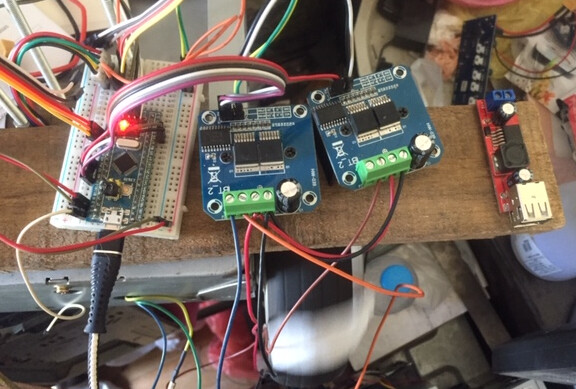
I used the example code in the library for open-loop and closed-loop with hall sensors, all with 3pwm driver with configured pwm frequency and an enable pin for each phase (I can see that in the picture, I don’t actually remember), but I guess that one can be done with a single enable pin shared on all three phases. I don’t remember the pins used.
BTS7960 requires 5V power so that’s an annoyance if you have a 3.3v MCU.
Two of these modules will give you 4 phases. One PWM + ENA pin on the module will output one phase.
If you look at the module on the right on the photo, that one has only one phase used.
I can compare with L6234.
2xBTS7960 gives some cogging, while L6234 works very smooth without any cogging.
But L6234 becomes very hot, unlike BTS7960 becomes barely warm.
I tried PWM frequence from 10 to 50000. No difference.
But may be my motor works beyond its means, and I need to try a little more powerfull motor.
Lower the pwn to obtain smoother rotation. I forgot to mention that in my initial post - 5k is what worked for me because the sound with hoverboard motor is very irritating on lower frequencies.
@Valentine mentioned on one post some tests and the optimal frequency of the BTS to be much lower than the 5k I used here.
BTS are designed for automotive use in a sealed box, so you won’t really hear anything because is in the engine compartment. Using them like that outside without any noise suppression is extremely loud and annoying. 5k may be the upper limit where you could still use them without burning a hole in the PCB.
I had a mistake in code: set driver.pwm_frequency after driver.init();
When I wrote this correctly, the pwm_frequency begin to play the role.
Yes, you are right: lower the pwm to obtain smoother rotation.
But “sound with motor is very irritating on lower frequencies”.
So the pwm_frequency is a compromise between smother rotation and noise.
You should start with the driver test code (no motors attached), and work your way up in the setup (openloop, hall sensor test, closed loop). Keep testing voltages relatively low until you understand what you are doing - hoverboard motors are low ohm, they consume a lot of current.
#include <Arduino.h>
#include <SimpleFOC.h>

BLDCDriver3PWM driver1 = BLDCDriver3PWM(PB1, PB0, PA7, PB10);

void setup() {
  Serial.begin(115200);
  // pwm frequency to be used [Hz]
  // for atmega328 fixed to 32kHz
  // esp32/stm32/teensy configurable
    driver1.pwm_frequency = 5000;
    // power supply voltage [V]
    driver1.voltage_power_supply = 12;
    // Max DC voltage allowed - default voltage_power_supply
    driver1.voltage_limit = 12;
    // driver init
    driver1.init();
    // enable driver
    driver1.enable();
  _delay(1000);
}

void loop() {
    // setting pwm
    // phase A: 3V
    // phase B: 6V
    // phase C: 5V
    driver1.enable();
    driver1.setPwm(3,6,5);
    delay(3000);

}
On the open loop test, I suggest you lower the voltage to 3-6V.
The code I am sharing is for STM32 BluePill. The BTS PWM pins should be attached to PB1, PB0 and PA7 pins, and EN attached for all three phases to the PB10 pin.
I’m a Uni Student developing bldc based robotic actuator. I need a BLDC driver; most of them are quite expensive, and the L6234-based one has a very low current limit. I was looking into dual BTS7960, which seems interesting. It would be very helpful if you shared the schematics and the code.