2x BLDC control schematic


I am developing my own board that includes STM32 blue pill, 2x L6234, 2x GBM4108H-120T gimbal motors, 2x AS5048-EK-AB magnetic encoders (SPI bus) and 2x GY-521 (MPU6050) gyros (I2C bus).

I made my schematic with the help of SimpleFOC schematic. Some explanation for reading my scheme: D1_A means driver 1, A wire of the motor (DRIVER1, DRIVER 2)(wires of the motor A,B,C, enable is EN).
Top left, marked with JP11 and JP12 are magnetic sensors, under them there are both GY-521s, top middle my STM32 blue pill, top right my voltage regulator L7805, and under all of that my motor drivers with output pins and all the wiring.

I have a couple of questions about my schematic;

  1. Is this a good way to power my electronics? My battery is 14.8V and i drop it down to 5V using L7805.I power my drivers with 14.8V (Vcc = 14.8V). With 5V i feed STM32 into 5V pin, and both GY-512s. Then i power my magnetic encoders with 3.3V from stm32. I read AS5048 datasheet and it says that it needs 3.3V regulated power supply but i am not quite sure what that means. Also, i am concerned about the way i power my STM32 blue pill - it works on 3.3V.
  2. Do encoders need pull-up resistors when in SPI mode?
  3. In schematic i am powering my drivers with Vcc, and Vcc is on SimpleFOC shield connected to the ground by C1 and CAP1 (see SimpleFOC schematic) in my schematic, i only have one set of these two elements, have i done it the right way? But i do have two sets of shotkey diodes and C2 and C4, so i also have 2 different VBOOT and VCP. Is that the right way?
    4.My EN1, EN2, EN3 pins are all connected to an output on my stm32, and if i understand correctly, this pin is always on digital HIGH, so if i put it on digital LOW, one of my motor 1 is not working, so theoretically i could connect it to 3.3V
  4. Do you see any more errors with my schematic that i did not mention?

I recommend you use some sort of buck converter to drop from 14.8 to 5V instead of the 7805, and then use a LDO like the 1117 for the 3V3 line. The 7805 is very inefficient and can get damaged if the power loss is too big so you might need a beefy heat-sink (depending on current draw and input voltage) to avoid damaging it. On the other hand, buck converters are much more efficient and this is relevant if your device is going to be battery powered.

1 Like

Hi,

Exciting projectI I think you’ll find some good advice here, I think there are many people working on similar kind of designs, including some that are very advanced.

Some comments from my side (but I think there are more qualified people):

  1. You should not power the 14.8 down to 5V using a regulator - this will probably overheat, and at least waste huge amounts of power. Use a buck converter, like David suggests. Then use a regulator to go from the buck converter output (make that maybe 5-6V) to the 5V and 3.3V. The TPS63061 is a nice buck converter if you plan to do it on your board, or there are millions of tiny inexpensive modules you can buy.
  2. No pull ups required on the bus except the CS line should have a pull-up, 10k is a suggested value I have seen.
  3. Someone with more experience of the N-channel drivers should say… I don’t know.
  4. For the EN lines, they can be useful to “stop” the motor without power. If you tie them high you will always have PWM on the lines, and this will produce noise and draw power (even if only a little) when the motor is stopped. Also, there is a danger if the IN pin is high with no PWM, for whatever reason, then you will have 100% on for that phase, a good way to burn drivers and motors through software bugs. If you use the EN pins you can switch the phases off when the motor is not being used - much safer. I speak from experience here: I tied my ENs high with pull-ups in my current design, and I now regret it. One thing you could do is drive them from the same MCU pin, if you have no need to disable the phases separately…

Regards from Vienna,

Richard

1 Like

You are missing all decoupling capacitors, and some more things that are recommend for STM32F1303C8T6.

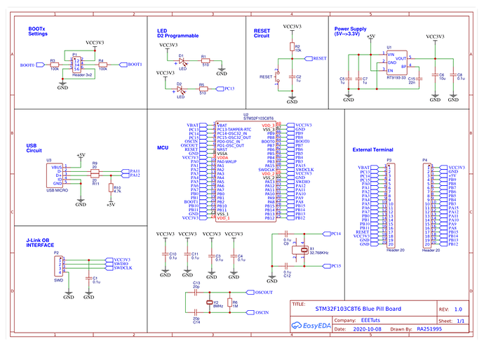
You can read Getting started with STM32F10xxx hardware development that explains what the MCU need. You can also look others designs to see what others do like this one Blue pill schematicCaptura de pantalla 2021-01-16 a las 22.45.09

You can watch some videos on this channel that explains how to design and power boards with SMT32 KiCad STM32 Hardware Design - An Overview in 20 Minutes
1 Like

Another few more things, looking at your schematic:

  1. The I2C Bus lines SDA and SCL should be pulled UP, not down…
  2. The STM32 also wants some capacitors, and in general maybe more attention to powering everything. Something like this is suggested for the STMs on the power side:

    Note that the capacitors C7 - C10 should be placed close to the VCC pins of the STM chip. Oh, and all the VCC and GND pins of the MCU need to be connected, but I guess its not finished yet…
1 Like

Regarding decoupling capacitors others have mentioned. Are you intending on literally using blue pill (which will include these capacitors) or using the same chip as the blue pill?

Have you checked pwm/timers? This is an are I’m not massively experienced on but you are using pa0 and pb0 for pwm. I have a feeling that then both being 0 means that they are on the same timer and I’m not sure you a timer can pwm 2 pins. Anyone else more knowledgeable?

1 Like

I am using STM32 blue pill board, like this one: image
No, i haven’t checked pwm/timers but if i unserstand correctly, I should connect all of the PWMs on same port, for example all 6 PWMs on PA like this: image

Also, my concern is 5V tolerance. All of the PWM pins in upper picture aren’t 5V tolerant, andi am not quite sure if this is important, but I was reading this github page, and author says: “Be careful with those NOT 5V tolerant pins. If you connect a 5V operated buffer/driver, that has pullups on it’s inputs you could ruin your microcontroller.”

The L6234 can be driven with 3.3V. You won’t be connecting the PWMs to 5V, so it should be fine to use any pin.

I corrected the schematic, so it now looks like this:


I added L1117 to drop 5V down to 3.3V, so now i can power STM32 blue pill board and AS5048A magnetic sensors. I also pulled SDA, SCL and SS pins to 3.3V. Unfortunatelly i don’t have a buck converter, but i do have a heatsink for L7805.
You mentioned that my schematic doesn’t have any decoupling capacitors, but I have my STM32 microprocessor on a blue pill board like this: image

Flip the board … you will see that there are many more components necessary for the board to function properly :slight_smile:

The new schematic looks better already!

Here is another thought (also based on experience): think about the ports you’re putting on there, and their pin-order. Perhaps you have done so already, but I didn’t, and its another thing I regret about my otherwise working designs.

For example, it is usual (though by no means universal) for pin 1 of any header/port to be GND. Doesn’t have to be, but if you stick to it your design will be easier to understand and use.
And for the I2C, what connection will it be? Is it a pin-header? Then you can solder stuff in any order, but if you make it the right order, it can be far more convenient… it looks like you will attach the GY521 sensor there, so if you match it’s pin-order and pin-pitch, then you can solder it on directly, or with a header.
If you’re planning to use a plug, then consider changing the pin-order: there is the Kwik/StemmaQT standard for routing I2C over JST-SH 1.0 4-pin plugs… if you stick to that standard there will be many compatible I2C devices, including multiplexers, bus-extenders, etc… that you can just plug in.

Another point now that I look at the I2C plug: you have tabled it +5V. But the GY521 can be powered with 3.3V, and your bluepill will use 3.3V, so make everything 3.3V. Otherwise, use a buffer to separate the 3.3V and 5V I2C Bus sections…

I don’t understand what is wrong, do i need more capacitors? I already tested the board and i succesfully uploaded blink code on it.

Hiya,

Yeah, basically some 100nF capacitors, placed close to the STM32’s VCC pins. I believe ST recommends 2 x 100nF per VCC pin in some application note somewhere. Your chip has 2 VCC pins, so 4 caps needed.

But I have a doubt… maybe it is a misunderstanding. Is your board integrating the STM32 chip, or is it a carrier board for the finished BluePill board? If you are putting the MCU chip on your board, you need those caps. If you are putting the whole bluepill board on there, in that case you don’t need any more capacitors, because they are already on the BluePill board…

In that case you also don’t need the 3.3V regulator, because the BluePill board has one on-board.

But you should look at your I2C port - it should probably be running at 3.3V, not 5V, for interfacing with a BluePill.

yes, i already have finished bluepill board and yes, i changed I2C to run at 3.3V. Currently working on PCB layout btw