Hi everyone,
I’m new in this field, so first of all, thanks a lot for the authors and contributors of this library, it really helps me to start in BLDC driving.
I am making a 2 axis gimbal stabilizer, which will be used for precise pointing application. Here is my setup, divided in three parts with one MCU for each:
Motor control: One MCU (STM32L476) to control 2 motors. Drivers: 2x DRV8316, Motors 2x GM8112 with encoders (AS5048).
Inertial computing: The second (main) MCU (STM32L476) which achieve sensors fusion from the IMU and the magnetometer (LSM6DSO+LIS2MDL).
HMI: A third MCU (STM32F072) is used for handle joystick and screen (the HMI is deported from the rest of the system and communicate with the main MCU via RS485/UART)
(All electronics card are custom board)
The main MCU compute the error between actual angle (measured from sensors) and setpoint (adjustable with the joystick). The error is then sent to motor control MCU. I use simpleFOC in velocity mode as PID speed controller and the input is the error with a gain (P controller).
Here is a diagram of my actual system for one axis:

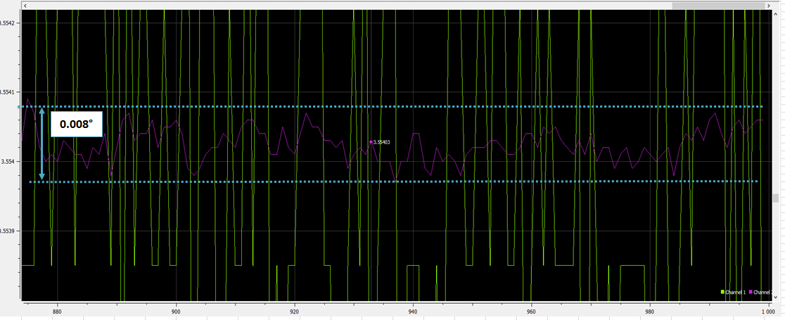
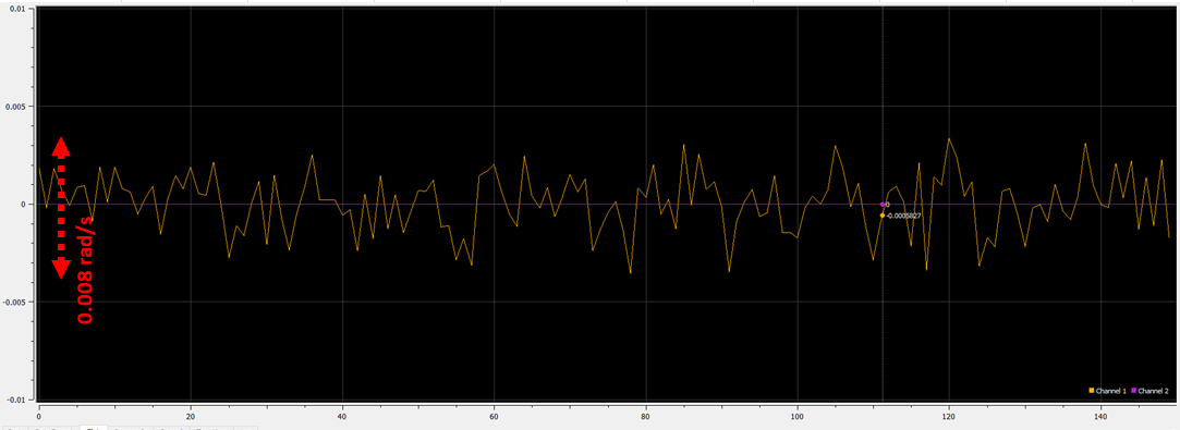
Note: as we can see on the diagram, I added a Kalman filter to my angle sensor measurement in order to reduce the noise from 0.15° to 0.008°, it help me to reduce a lot the motors vibrations and audible noise.
In term of timing, the angle error is sent at 100Hz by the main MCU via UART (921600 bauds) The Simplefoc specific part is call on interrupts at 4000Hz for both motors.
Initially I tuned the system parameters by evaluate different aspects:
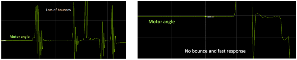
- The response of the motor to a small disturbance when speed =0
I set speed =0 and manually apply a small disturbance to the motor, so I can adjust the parameters until getting a fast response and no bounce
- The precision with which the motor maintains its setpoint angle.
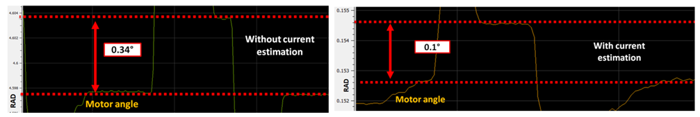
I add current estimation to improve the holding torque and the precision (by providing phase resistance and KV rating at init (BLDCMotor(21, 4.5f, 20) )
When I set the speed setpoint to 0, and apply a small disturbance to the motor it remain to its original angle with an error range. The error is reduce from 0.34° to 0.1° with the current estimation.
- The smoothness at slow speed
- The audible noise of the motor or vibrations
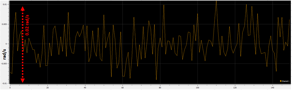
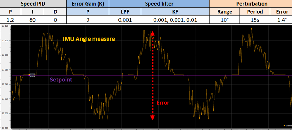
The final step was to estimate the stabilization efficiency, for that I had a platform which can incline the gimbal in 3 axis. For the YAW axis I apply a rotation of ±10° with a 15s period. The best results I get are with the parameters below. The gimbal keeps the target angle with 1.5° range of error. The accuracy isn’t that good but the main problem is the little shaking, we can see on the picture below the little spikes at high frequency.
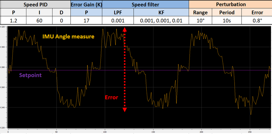
I get the same issue for the PITCH axis and the best I can have, is with those settings,
By doing some tests I see that the vibrations may vary, depending on the support on which the stabilizer is mounted… (I try to mount the gimbal on silent blocs and it’s even worse as it create some counter reaction between gimbal and the base)
So I would need some help to find a way to reduce the shaking and also to reduce the error range… If you have some ideas to better tune the parameters or any other suggestions to improve my actual system, I would really appreciate that :).
(For more setting details I join a simplified code for the motor control part)
//[…] Includes
// Private functions prototypes
void Update_IT_callback(void);
// Encoders
MagneticSensorSPI sensor_YAW = MagneticSensorSPI(CS_ENC_YAW, 14, 0x3FFF);
MagneticSensorSPI sensor_PITCH = MagneticSensorSPI(CS_ENC_PITCH, 14, 0x3FFF);
// BLDC Driver
// GM8112 motor: 36N42P → 21 pp ; 4.5 Ohm ; 400rpm/20V → 20KV
BLDCMotor motor_YAW = BLDCMotor(21, 4.5f, 20);
BLDCMotor motor_PITCH = BLDCMotor(21, 4.5f, 20);
// phA, phB, phC, CS
DRV8316Driver3PWM driver_YAW = DRV8316Driver3PWM(INHA_YAW, INHB_YAW, INHC_YAW, CS_DRV_YAW, false);
DRV8316Driver3PWM driver_PITCH = DRV8316Driver3PWM(INHA_PITCH, INHB_PITCH, INHC_PITCH, CS_DRV_PITCH, false);
// Seria Pins linkage
HardwareSerial Serial1(PB7, PB6); //RX, TX
// Flag and variables
float target_speed_YAW = 0;
float target_speed_PITCH = 0;
int read_OK =0;
int trame_OK =0;
void setup()
{
//Timer configuration
TIM_TypeDef *Instance = TIM3;
HardwareTimer *MyTim = new HardwareTimer(Instance);
MyTim->setOverflow(4000, HERTZ_FORMAT); // 4000 Hz
MyTim->attachInterrupt(Update_IT_callback);
// Init serial port
Serial1.begin(921600); // UART connected with main mcu

// Init magnetic encoders
_delay(100);
sensor_YAW.init();
sensor_PITCH.init();

// link the motor to the sensor
motor_YAW.linkSensor(&sensor_YAW);
motor_PITCH.linkSensor(&sensor_PITCH);

// driver config
driver_YAW.voltage_power_supply = MAX_SUPPLY_VOLTAGE;   // Volts
driver_YAW.voltage_limit = MAX_SUPPLY_VOLTAGE;			// Volts
driver_YAW.init();

driver_PITCH.pwm_frequency = 25000;
driver_PITCH.voltage_power_supply = MAX_SUPPLY_VOLTAGE;
driver_PITCH.voltage_limit = MAX_SUPPLY_VOLTAGE;
driver_PITCH.init();

// link the motor and the driver
motor_YAW.linkDriver(&driver_YAW);
motor_PITCH.linkDriver(&driver_PITCH);

// choose FOC modulation
motor_YAW.foc_modulation = FOCModulationType::SpaceVectorPWM;
motor_PITCH.foc_modulation = FOCModulationType::SpaceVectorPWM;

// set torque mode
motor_YAW.torque_controller = TorqueControlType::voltage;
motor_PITCH.torque_controller = TorqueControlType::voltage;

// set controler type
motor_YAW.controller = MotionControlType::velocity;
motor_PITCH.controller = MotionControlType::velocity;

// velocity PID controller parameters
motor_YAW.PID_velocity.P = 1.6f;
motor_YAW.PID_velocity.I = 80.0f;
motor_YAW.PID_velocity.D = 0.000f;

motor_PITCH.PID_velocity.P = 1.2f;
motor_PITCH.PID_velocity.I = 60.0f;
motor_PITCH.PID_velocity.D = 0.000f;

motor_PITCH.PID_velocity.output_ramp = 2000;
motor_YAW.PID_velocity.output_ramp = 2000;

motor_YAW.current_limit =4.0f; // Amps
motor_PITCH.current_limit = 4.0f; // Amps

motor_YAW.voltage_limit = MAX_SUPPLY_VOLTAGE; // Volts
motor_YAW.PID_velocity.limit = motor_YAW.voltage_limit;

motor_PITCH.voltage_limit = MAX_SUPPLY_VOLTAGE; // Volts
motor_PITCH.PID_velocity.limit = motor_PITCH.voltage_limit;

// velocity low pass filtering time constant
motor_YAW.LPF_velocity.Tf = 0.001f;
motor_PITCH.LPF_velocity.Tf = 0.001f;


// maximal velocity of the position control
motor_YAW.velocity_limit = 0.4f;
motor_PITCH.velocity_limit = 0.4f;

// init motor hardware
motor_YAW.init();
motor_PITCH.init();

//Init YAW FOC
int init_FOC_state =0;
init_FOC_state  = motor_YAW.initFOC();

if(init_FOC_state !=1)
{
	HAL_NVIC_SystemReset(); //reset uC if init failed
}

//Init PITCH FOC
init_FOC_state = motor_PITCH.initFOC();
if(init_FOC_state !=1)
{
	HAL_NVIC_SystemReset(); //reset uC if init failed
}


//Synchronisation sequences with external MCU via UART...
//[ ... ]
//


//Start 4000Hz interrupts for SimpleFOC specific part
_delay(100);
MyTim->resume();
}
void loop()
{
trame_OK =0;
read_OK = receive_Serial(); //handle UART event: Check if datas are available on RX and read them (non blocking function)
if(read_OK == 1)
{
	trame_OK= extract_datas(&uart_datas);	//extract datas from UART frame
	if(trame_OK ==1 )
	{
		if(uart_datas.op == CMD_WRITE_SETPOINTS)   //check for command code, then set target speed
		{
			//Set PITCH target speed
			if(abs(uart_datas.PITCH_error) < (0.01f* FROM_DEG_TO_RAD))
			{
				target_speed_PITCH = 0.0f; 		//stop motor if 0.01° of precision is reach
			}
			else
			{
				//Apply (K) gain on the error
				target_speed_PITCH = 17.0f*uart_datas.PITCH_error;
			}

			//Set YAW targer speed
			if(abs(uart_datas.YAW_error) < (0.01f* FROM_DEG_TO_RAD))
			{
				target_speed_YAW = 0.0f;	//stop motor if 0.01° of precision is reach
			}
			else
			{
				//Apply (K) gain on the error
				target_speed_YAW = 9.0f*uart_datas.YAW_error;
			}

		}

		//Check for motor physical angle limits
		if((sensor_PITCH.getMechanicalAngle() >= PITCH_MOT_MAX) && (target_speed_PITCH>0))
		{
			target_speed_PITCH = 0.0f;
		}
		else if((sensor_PITCH.getMechanicalAngle() <= PITCH_MOT_MIN) && (target_speed_PITCH<0))
		{
			target_speed_PITCH = 0.0f;
		}
	}
}
}
void Update_IT_callback(void) // 4 000Hz IT
{
motor_YAW.loopFOC();
motor_PITCH.loopFOC();
motor_PITCH.move(target_speed_PITCH);
motor_YAW.move(target_speed_YAW);
}