I got the Adafruit one, so more credit to Lady Ada!
TBH the only thing I can find in the fuses as per the datasheet that is relating to USB is the factory calibration data - there shouldn’t be any need to change that.
It does require a specific clock setup for USB to work - but the boot loader should take care of that. Is your oscillator setup the same as for the feather?
Other than that the USB port wants certain resistances on its ID pin, I assume you have those? The differential trace impedance is important in theory, but I hear you can more or less ignore it for the low speed USB used by the MCUs.
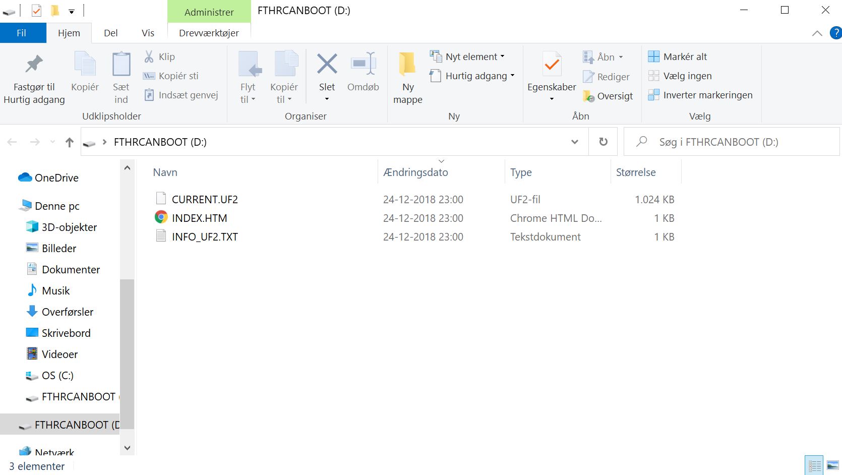
Hay, I found the bug. Its a hardware bug. I assumed the USB plug was soldered properly in, but it turns out it is a wrong part, compared to the footprint. Quite embarrassing. Good the USB lines are broken out.
Unfortunately its not al well and dandy. I have been to optimistic about the step-down regulator design. Its not working as intended. I should be able to solder in the power for the bridge driver and test, but it is somewhat a setback. Will find another solution. Im tempted to use a integrated step-down module but they are expensive. There are several other small mishaps, so have to order PCB again no matter what. I guess this is the process of developing hardware. Human error factor The LED is blinking away in RGB colors, so there are some progress. This means I can test the hall sensors on the analog inputs.
Hoocked up 12v from my 3D printer´s PSU. The converter steps down to 10v and the 500mA LDO steps down to 5v. Unfortunately the enable pin on the USB power switch does not turn on when floating. The 3.6v LDO does work when USB and PSU (12v) is connected. So no issues when connected to PC and PSU is ON!
The Half-bridges and gate drivers are functioning.
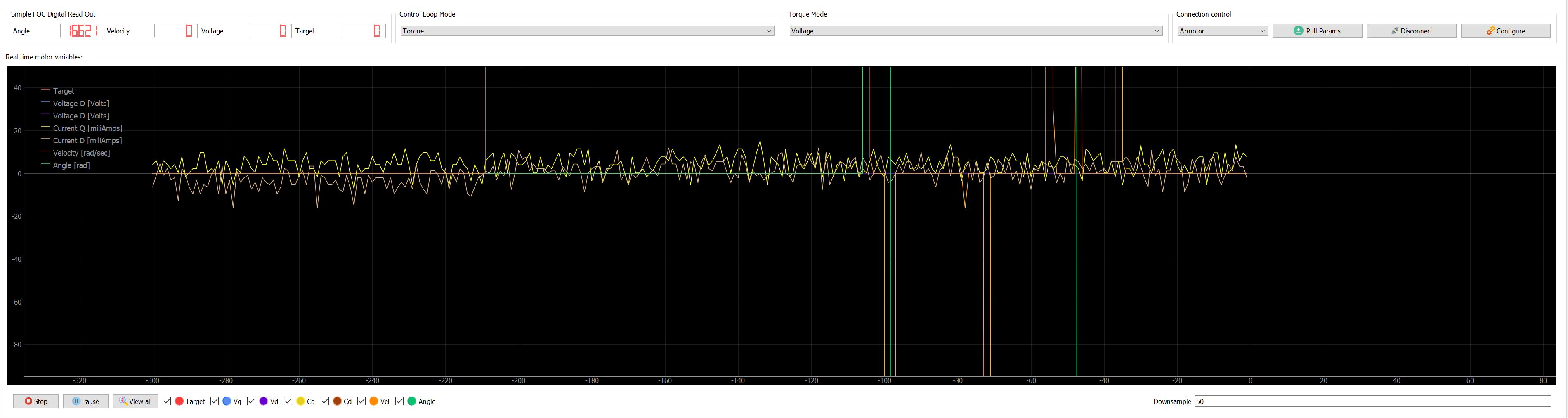
Current sensor are reacting to led test setup, but should be inverted. At no current the analog value (10bit) are around 450. This value decreases when PWM on the switches is increased.
How should I set up the current sensors?
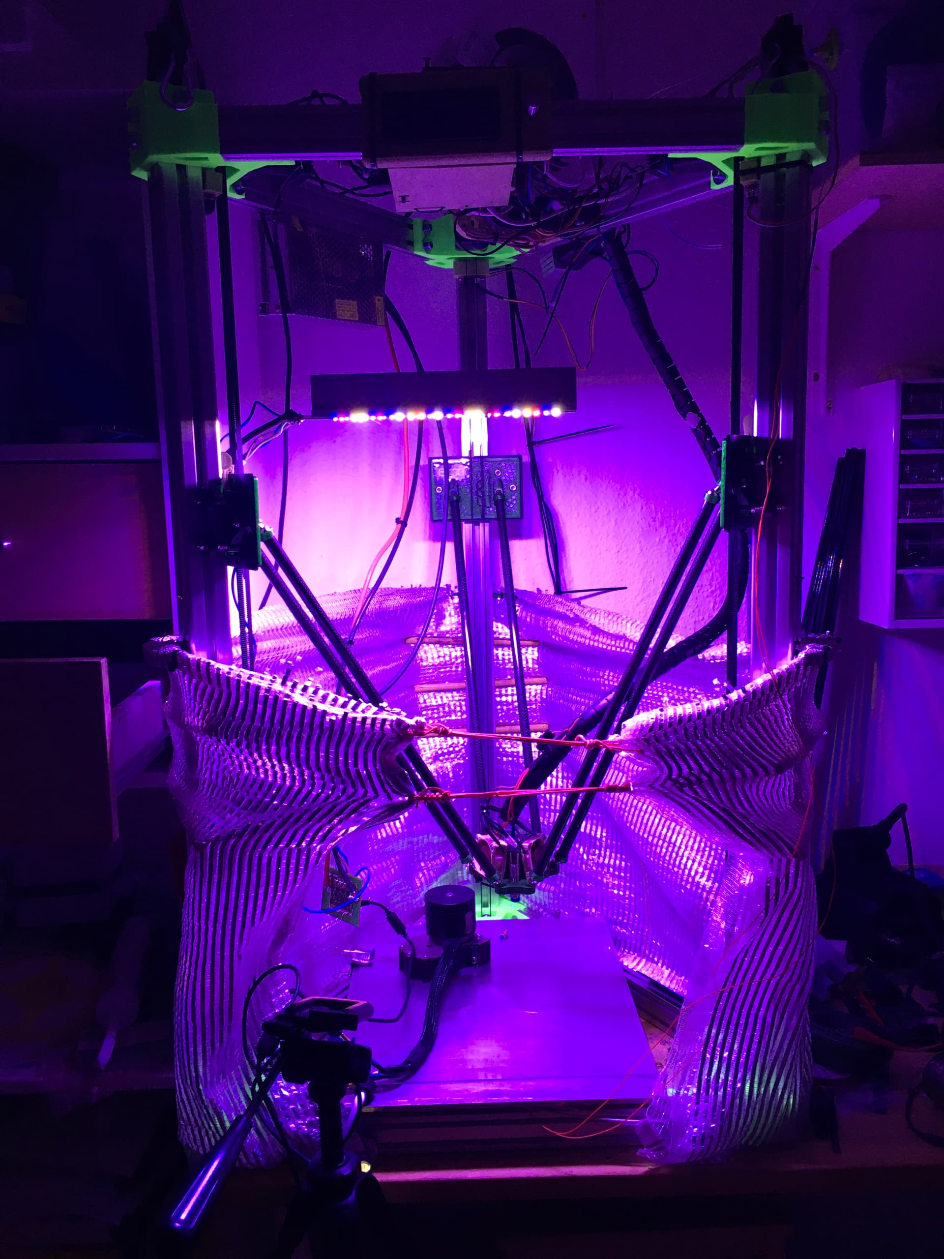
Here is the LED test rig. Will need to borrow a photon flux sensor. It would be interesting to se a comparison between a fully blue and red lamp vs mixed white, blue and red.
Managed to activate ADC1 by writing to the registers. The feather M4 Can does not use ADC1, for some reason.
I can now read board temperature (main power line) and voltage.
When cranking up current on the LED setup, I do see a slight increase in temperature. This is without a copper busbar.
volatile uint16_t ain8_read;
volatile uint16_t ain9_read;

//These values are in the datasheet
#define RT0 10000   // Ω
#define B 3624      // K
//--------------------------------------


#define VCC 3.6    //Supply voltage
#define R 10000  //R=10KΩ

//Variables
float RT, VR, ln, TX, T0, VRT, VRT2, VOLT;

float read_adc1() {
  // enable and read 2 ADC temp sensors, 12-bit res

  SUPC->VREF.reg |= SUPC_VREF_TSEN | SUPC_VREF_ONDEMAND;
  ADC1->CTRLB.bit.RESSEL = ADC_CTRLB_RESSEL_12BIT_Val;
  while (ADC1->SYNCBUSY.reg & ADC_SYNCBUSY_CTRLB); //wait for sync
  while ( ADC1->SYNCBUSY.reg & ADC_SYNCBUSY_INPUTCTRL ); //wait for sync
  ADC1->INPUTCTRL.bit.MUXPOS = ADC_INPUTCTRL_MUXPOS_AIN8;
  while ( ADC1->SYNCBUSY.reg & ADC_SYNCBUSY_ENABLE ); //wait for sync
  ADC1->CTRLA.bit.ENABLE = 0x01;             // Enable ADC

  // Start conversion
  while ( ADC1->SYNCBUSY.reg & ADC_SYNCBUSY_ENABLE ); //wait for sync

  ADC1->SWTRIG.bit.START = 1;

  // Clear the Data Ready flag
  ADC1->INTFLAG.reg = ADC_INTFLAG_RESRDY;

  // Start conversion again, since The first conversion after the reference is changed must not be used.
  ADC1->SWTRIG.bit.START = 1;

  while (ADC1->INTFLAG.bit.RESRDY == 0);   // Waiting for conversion to complete
  ain8_read = ADC1->RESULT.reg;

  while ( ADC1->SYNCBUSY.reg & ADC_SYNCBUSY_INPUTCTRL ); //wait for sync
  ADC1->INPUTCTRL.bit.MUXPOS = ADC_INPUTCTRL_MUXPOS_AIN9;
  // Start conversion
  while ( ADC1->SYNCBUSY.reg & ADC_SYNCBUSY_ENABLE ); //wait for sync

  ADC1->SWTRIG.bit.START = 1;

  // Clear the Data Ready flag
  ADC1->INTFLAG.reg = ADC_INTFLAG_RESRDY;

  // Start conversion again, since The first conversion after the reference is changed must not be used.
  ADC1->SWTRIG.bit.START = 1;

  while (ADC1->INTFLAG.bit.RESRDY == 0);   // Waiting for conversion to complete
  ain9_read = ADC1->RESULT.reg;


  while ( ADC1->SYNCBUSY.reg & ADC_SYNCBUSY_ENABLE ); //wait for sync
  ADC1->CTRLA.bit.ENABLE = 0x00;             // Disable ADC
  while ( ADC1->SYNCBUSY.reg & ADC_SYNCBUSY_ENABLE ); //wait for sync


  return (ain8_read, ain9_read);

}


void setup() {
  Serial.begin(115200);
  while (!Serial);
  delay(1000);

  T0 = 25 + 273.15;
}

void loop() {

  analogWrite(10, 5);
  analogWrite(11, 5);
  analogWrite(12, 5);
  analogWrite(13, 5);

  read_adc1();
  Serial.print(ain8_read);
  Serial.print("\t");
  Serial.println(ain9_read);

  //  Calculate temp  //
  VRT = ain8_read;              //Acquisition analog value of VRT
  VRT = (3.285 / 4096.00) * VRT;      //Conversion to voltage
  VR = VCC - VRT;
  RT = VR / (VRT / R);               //Resistance of RT

  ln = log(RT / RT0);
  TX = (1 / ((ln / B) + (1 / T0))); //Temperature from thermistor
  TX = TX - 273.15;                 //Conversion to Celsius

   //  Calculate voltage  //
  VRT2 = ain9_read;
  VRT2 = (3.285 / 4096.00) * VRT2;
  VOLT = VRT2 * (14.8/1.1);

  Serial.print("Temperature:");
  Serial.print("\t");
  Serial.print(TX);
  Serial.print("C\t\t");
  Serial.print("\t");
  Serial.print(VOLT);
  Serial.print("VOLT\t\t");
  Serial.print(TX + 273.15);        //Conversion to Kelvin
  Serial.print("K\t\t");
  Serial.print((TX * 1.8) + 32);    //Conversion to Fahrenheit
  Serial.println("F");


  delay(30);


}
[Edit] I see there is a significant voltage drop on the PSU (main power). The PSU will start to make this high pitch sound as if it is overloaded. This is when I turn op the current on the LEDs. I have a 500W PSU somewhere in a old cabinet. Think I will use that.
Just soldered another 0.03 resistor on top, so it should have 0.015 ohm resistance now with a 50 gain, on a 24v PSU with large caps.
I do se some movement like a rotation, when the initFoc does sensor calibration, it does not seem to compute the actual movement or maybe the phases are not setup right. Hmmm I thought it was supposed to be simple


 ATSAME51 CAN interface")