
That wiring seems correct to me.
In this case the following signals should have the same polarity: PWM_A[0], PWM_A[1] and PWM_A[7]
and these ones should have the same polarity: PWM_B[0], PWM_B[1], PWM_B[7].
And these two groups should have opposite polarity to each other.
The three pairs PWM_A[0], PWM_B[0] ; PWM_A[1], PWM_B[1] and PWM_A[7],PWM_B[7] these pairs should always share the same duty cycle. But the duty cycle can be different between the different pairs.
In your picture we see three signals that look in-phase. These are then presumably either PWM_A[0], PWM_A[1] and PWM_A[7] or PWM_B[0], PWM_B[1] and PWM_B[7] ?
The signals in the image are actually the outputs of the driver (U,V,W), seen on the right side of the board.
Experiment with 2 rads per second, not 200. Check everything at every stage to see it’s operating the way you are hoping and you will isolate the problem far faster than trying to get a quick solution through the forum, at last that usually works for me…
Ok, so at that level the picture looks ok to me. If you zoom out further we should be able to see if the pattern matches what we’d expect to get from a working commutation…
The problem if I understand correctly, is that the motor simply won’t move, and you’ve now tried 3 different MCUs?
The driver is outputting PWM, so this actually seems ok.
You don’t perchance have another motor to try out with?
And the code is still the one from above?
I’m a little confused why you wouldn’t see any motion at all… that’s quite weird.
Hey guys,
I’ve gone through the Teensy code and we have a bug in the code. It has been corrected in the dev branch
The issue has arised due to multiple changes in the low-level API as the 6pwm for teensy boards was added the last, the pwm writing function was did not comply with the new api and was never called. Making the driver stuck in the initial position (all the phases at half of the duty cycle).
So if you use the dev branch library this issue should be removed.
@runger. Sorry for the delay in response. I’ve been working on several projects at once, and this one got pushed back a bit. I’m a bit confused, because the most recent oscilloscope image I provided up above shows the three phase wires going into the motor (so the outputs of the motor driver). They are all PWM-ing, but they are in phase. I thought that the outputs of the driver should be out of phase when commanding a velocity? I’m not super well versed on this, but I thought that the commutation should be trying to resemble some sort of sine wave (or something of the sort).
The code is all the same except that I am now specifying the correct pins for the Pico. I also removed all of the things you said to remove, like driver.enable(), and I’m not commanding a specific velocity in motor.move(). I’m just using the serial monitor to change the commanded velocity.
The way this works is that the PWM waveform controls the driver’s half-bridges, switching the FETs on and off very quickly. The PWM waveforms are in-phase, in the case of a 3-PWM driver one single PWM signal controls a half-bridge, and the driver hardware switches both FETs based on this one input.
While the PWMs of the different phases are in-phase, the duty cycle between them is different. It is the duty-cycle of the PWM that encodes the sine waves for the commutation.
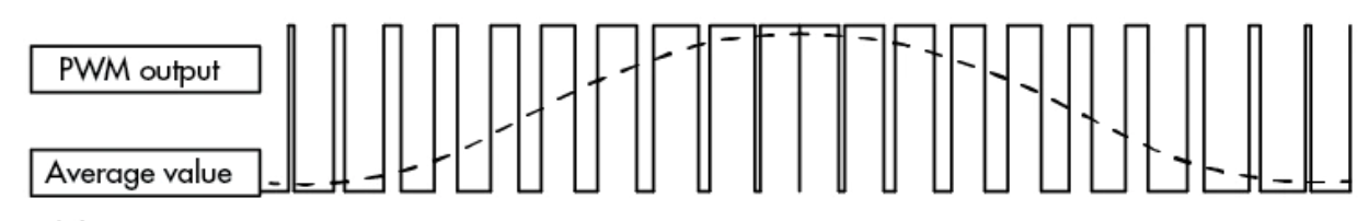
The motor is an inductive load, which can’t react at the speed of the PWM signal. It “smooths” the PWM into an analog voltage, the level of which depends on the PWM duty cycle.
I would append that it’s the current that gets smoothed. If you actually look at the output with an oscilloscope, you can see the voltage jumping around like crazy due to the PWM. However, if you use a sense resistor to measure the current then you can see it changing in a nice sine wave manner.
The way the inverter works causes a number of complications. I encountered some when I tried to measure the current across two phases at once with my oscope, for instance. My oscope shares a ground between probes (which is not the best approach and probably not a thing for better scopes). This made in necessary to use a capacitor and stuff to sample the voltage across the resistor. If I just connect the ground of the probe to the actual power ground, the voltage from the pwm overwhelms the signal from the sense resistor. If I connect both grounds of both probes just across the sense resistor, things similarly get complicated.
It’s close to a 3 phase sine wave when it comes to current, but that intermediate stage does cause complications that are worth being aware of.