Great, and wish you success.
Valentine
PS When is your thesis due?
Great, and wish you success.
Valentine
PS When is your thesis due?
Not wery soon. In the next year. This is my 3d year of 4
Hey, @German_io ,
There are actually many good sources for this information online, but it isn’t so easy to reverse engineer these equations. My guess is that friction is modelled differently, but it would be a lot easier with more context, i.e. the full reference so we could check the derivation and explanation of the terms…
I think it’s an excellent bachelor project, and you’re starting at the right time.
Hello everyone, i don’t know if thia question has been answered somewhere or not.
In each balancing robot and lqr controller u should use angular velocity out of your sensor? How do you do that?
I have a module that outputs filtered angle. Forst thought i got two values and divided to the time to get angular speed but the measurements are soooo noisy and inacurate.
How do you guys get velocity from an imu?
Do you have any detailed requirements about the motor driver? Also, any budget restrictions?
The reason I’m asking is I’m designing a few drivers however they are not cheap to manufacture. I could post the schematics and you need to manufacture yourself. It’s easy to order. I am making sure everything is in stock.
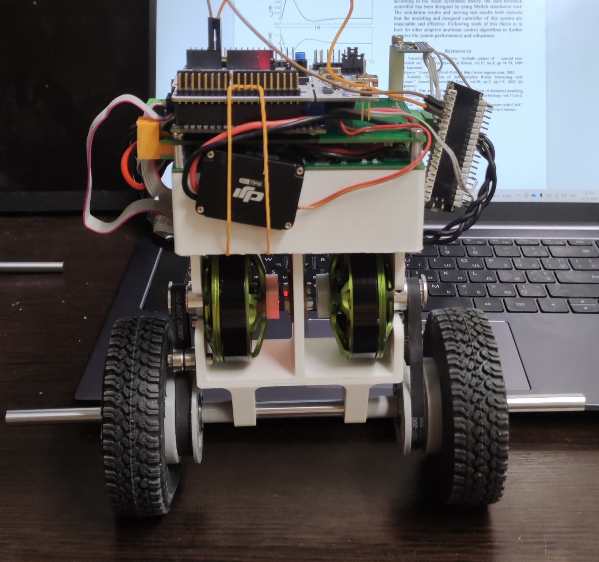
So, this is my current robot. It first model for testing code and idea. But is works perfectly. Now i plan to do electronics smaller (not use nucleo) and use my own stm32 board. May be next vestion will be some bigger (this is 5010 motors and 90mm wheels). But now it wery powerful robot. I can hold it one hand on one wheel and motor does not heating
Very userful would be find a desing of smaller motor drivers (now im using drv8302 proto board from ali).
And i have not any budget restrictions (within reason)
Some small drivers designs would be nice
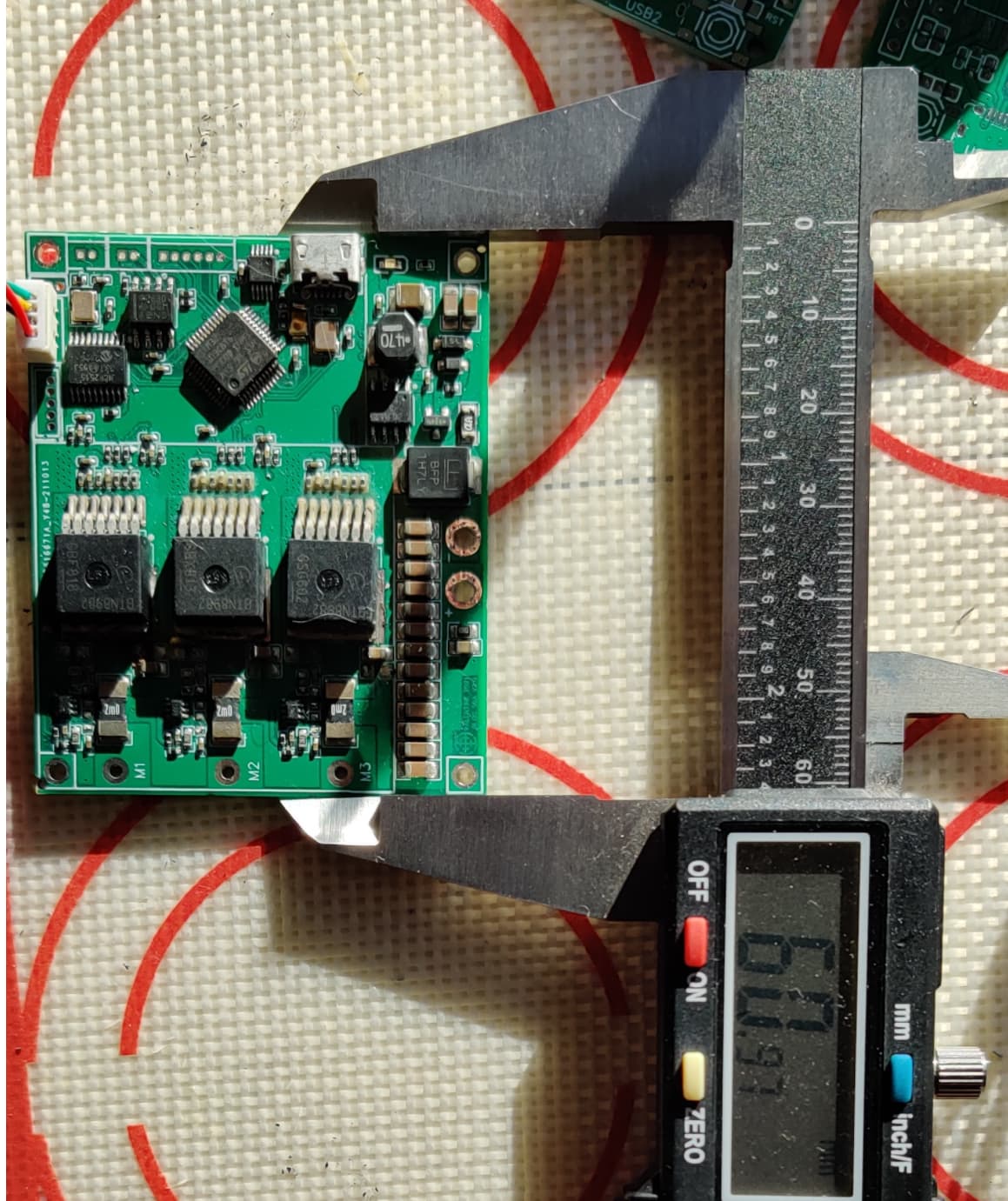
This is the board I’m designing now. High power (33A) , it’s in testing stage, and it works, 6x5cm, with integrated STM32F103, inline current sensing, ESD /overvoltage protection, CANBUS, SPI and UART. Problem is the mosfets are not in stock, and I’m redesigning the board from scratch.
I should be able to finish the design this week, and send to manufacture, so by end of January I’ll have a working prototype. If you are interested in testing, with no obligations, let me know.
Yes im interested. It seems wery interesing
How can i connect encoders to this board?
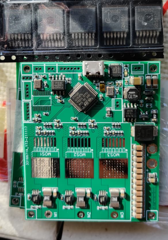
I have bare boards with the MCU only, no mosfets, if you can find the mosfets and solder them yourself, let me know DM privately, this is getting too much for the board. This is how the bare second version of the BTN board looks like, you need to solder the mosfets (if you can find them, I had a few left over).
I tried to find this but in all my country it out of stock
Yes, I know, that’s why I’m redesigning the board. I have some left but it’s not practical to keep working on a board that will be available a year from now.
Ok. I will wait for your design. Thank you.
Angular velocity - only gyro value. If I understand your question…
thanks for the answer
gyro gives acceleration and angle, how do you get velocity?
Is it possible to use speed and velocity from encoders for it ?
well i tried the same way
the encoders and sensors in library use simple derivation of values:
(theta2-theta1)/dt
i’m doing the same
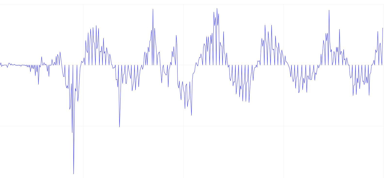
the problem is, i don’t get smooth values, because the angle is not perfect on it’s own and when you derive from it u get plenty of jumps. i managed to get smoother values by lpf on the velocity, but i was wondering if there was any other options.
smth like this:
I have same problems and correct data with LPF. Yes it have some delays. But i dont know any solutions for it. We can ask users with more experience
What in your graph? Gyro value? Acc? What is the time interval between scans?
After all, there are many examples online of using a gyroscope and acc. Want to invent something new?