Programming the Lepton from start to finish

Ok, I think I’ve gone about as far as I’m going to with this thing. I think angle mode is better off without it, but velocity mode is better with it. Maybe adding second order approximation (estimate the acceleration from velocity history) would get angle mode working better too.

I made a new thread to avoid monopolizing this one any further, and so it’s easier for people to find in the future. See the updated code there: SmoothingSensor: Eperimental sensor angle extrapoltion

Hey,

I have pushed Arduino Board files for the Lepton:

If you follow the install instructions of this repository (isn’t hard) then you will have the Lepton available as a board in ArduinoIDE, and things like Serial, I2C and SPI should just work.

If anyone decides to try it out, please let me know how it goes.

It took me a bit longer than anticipated because Arduino IDE is a pain. But now its working I think I can add more boards fairly quickly.

We’ll add more boards as we go along, I guess it only makes sense once they have a certain popularity.

2 Likes

I’ll give it a try within a few days, hopefully, I am still using the b-G431b-esc1 board because it has enough memory for my experimenting and stuff, but maybe I can at least use the leptons I had made. If they work ok I might roll with them for a bit but I don’t want to get more made because I want to use whatever everyone else is using, and I think the lepton’s memory is too small for it to catch on, however it’s great start and I feel like if you are going to put the effort in to make the files I should contribute by at least testing them, which takes much less time and expertise ;)…

edit:
I actually got inspired and gave it a quick try. The first issue is that the folder for the boards must be different for windows installs, and you must be using Linux or something. The folder for windows appears to be something in the region of: C:\Users\anthony\AppData\Local\Arduino15\packages

replace anthony with your own username.

However I don’t know for sure that is the right folder, it may be a subfolder or something. When I unzip to that location and start the ide, in the tools> board menu it now has an entry for simplefoc-main-stm32 bah blah or something. fairly long name that could be more clear…
Then within that there is a simplefoc board, which is perhaps the shield, and then there is one with a very long name that doesn’t display correctly which is probably the lepton? From looking at the directory structure of the stuff that was unzipped, I’m guessing so.

however, in the windows arduino, you have to select the board from the drop down in the main window, too. When I try to do that, the board with the long name is not there.

If I select the Simplefoc board, which does show up in that list, nothing works :(. I checked that the upload by SWD is enabled etc.

I think most of these problems stem from the differences between the linux arduino ide and the windows one.

I can keep trying more later, but am pretty baffled and it’s getting late.

edit: looks like my test file had an error in it, it seems to compile and upload, and Serial seems to work if you select the SimpleFOC board on the second in-window menu :slight_smile: I don’t know if this is the right board, or if it is just a coincidence that it works and thus if other features will work or what, but it is some progress :). I just uploaded a file that prints to Serial to see if Serial worked, I haven’t tried any of the other stuff yet, but will later :).

Lepton should be 64kb, not 32 as listed in that board file. This one: STM32G031G8U6 STMicroelectronics | C432211 - LCSC Electronics

Looks like I’ll need to update my IDE and STM32 library before I can test it… I’m still on IDE v1.8.

What all was involved in making it? I never was able to figure out what I was supposed to do. Are the files in variants/SIMPLEFOC_LEPTONG031 edited from the ones in packages\STMicroelectronics\hardware\stm32\2.3.0\variants\STM32G0xx\G031G(4-6-8)U_G041G(6-8)U, or created some other way? And is there a template for boards.txt, or do you just start with the monster packages\STMicroelectronics\hardware\stm32\2.3.0\boards.txt and strip it down to one definition, and edit from there?

Read this https://docs.arduino.cc/software/ide-v1/tutorials/PortableIDE
I find it much nicer to have the packages and libraries all in with the IDE itself. For example mine is C:\Arduino\portable\packages

No, that’s the application’s data folder. You can put it in there somewhere too, probably, but it’s supposed to go in your user Sketchbook folder, in the hardware subfolder. By default, the Sketchbook folders are located here:

image

Hmmm… Arduino IDE builds this name from the folder name “simplefoc_arduino_boards” and the architecture name “stm32”.
I’ll add a note to the instructions to rename the cloned folder to something shorter.

The shields don’t have on-board MCUs so they won’t be part of the board files.

Hey that’s great!

could you send a screenshot of what your menu you looks like?

You should have “SimpleFOC Boards” as the Board name, and then there is a Submenu (“Board Part Number”) which has the Lepton as the only choice ATM:

image

image

I’ve now changed that 32kB in the menu item name to be 64kB, thanks Deku! It was just in the label, the board definition used 64kB.

It was such a headache because Arduino IDE caches stuff internally and you have to restart it 1000 times (or at least, I don’t know how to re-initialize it).
But yeah, you copy a lot of stuff from the generic variant and adapt it. And the board.txt follows the same format as the main framework’s so you can copy things and adapt from there too…

1 Like

There was definitely no \hardware folder, I checked thoroughly. They changed a lot of stuff in the latest update for arduino apparently. Will get those screenshots later yeah, I’m on the wrong computer now. Actually I have arduino on this computer too, an older version, and I checked and there is no hardware file there either C:\Users\User\Documents\Arduino . Searched, put the folders in alphabetical order and searched manually, definitely not there, not hidden or anything.

Fair enough, if the hardware folder is not there, you can just create it. I’ve updated the docs to mention that :slight_smile:

Thanks for being part of the “test subjects” for this…

ok cool. BTW if anyone else wants a lepton let me know, me and Runger are the only ones that actually have any at this point so I feel kind of obligated…

here is a screenshot, probably it’s because of the wacky folder structure, I will try correcting it

Yeah, if you shorten the folder name to just “simplefoc” the menu will look better.

As for the “arduino-select-board” menu item, no idea what is up with this, it seems to be something the IDE puts there automatically… I have it too, and could not really figure it out.

It turns out there is a problem with the lepton’s waveform generation, even in open loop. There appears to be a thump about once per revolution. The waveform flakes out, I confirmed it in a couple different ways. I thought it was some kind of mechanical defect in my fan at first, that’s why I didn’t realize what was going on.

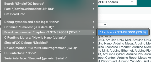
It appears to be worse when I compile code on my desktop. I reset the libraries, and it still is. I noticed my desktop gives the following error when compiling and uploading on arduino, after following the board install proceedure:
Warning: Board simplefoc:stm32:build doesn’t define a ‘build.board’ preference. Auto-set to: STM32_BUILD

In orange letters. I think maybe some peripheral is configured slightly differently and this has something to do with the thumping noise.

The G431 board doesn’t do it as far as I can tell. I hypothesize some calculation occurs when things wrap around and this causes the thump. Either I have to try to get in there and fix the problem with the code or I have to use the G431 board and can’t use the Lepton. I will have a look at the code but… This is a real downturn for me because I really don’t want to have to go through designing my own G431 based board.

The thump occurs even when I restrain the fan from actually moving or put the voltage down so low it can’t move on it’s own. So it’s definitely an interruption in the waveform.

edit: ok, looking at the code, I think it might be when the shaft_angle = _normalizeAngle(shaft_angle + target_velocity*Ts); happens on line 677 of BLDCmotor.cpp. Normalize calls fmod, floating point modulo.

The noise takes a while to build up when I start rotation, I think this may be because the division takes longer when the angle is larger? I think shaft_angle accumulates, rather than wrapping around.

Thus, perhaps the floating point hardware is not working properly on the Lepton? Man, I haz no clue how to solve such a problem :(. If only I can get open loop mode working at least.

Oh geeze it’s an M-0 cortex, right? they don’t even have floating point hardware? https://ww1.microchip.com/downloads/en/DeviceDoc/90003178A.pdf

Yeah the G431 thing has floating point hardware https://www.google.com/url?sa=t&rct=j&q=&esrc=s&source=web&cd=&cad=rja&uact=8&ved=2ahUKEwii1v2Zg-n9AhUcmYkEHY5LBA4QFnoECBEQAQ&url=https%3A%2F%2Fwww.st.com%2Fen%2Fmicrocontrollers-microprocessors%2Fstm32g431cb.html&usg=AOvVaw1IG0vpnrQS1R11KanU9eqJ

Ah shit.

Update: well I don’t see how I could make the code in the library work any better, which is no surprise. It doesn’t look like there is much stuff that could take time. There is just a handful of floating point modulo things and I don’t see anything that could explain the increase over time, shaft angle doesn’t increase in perpetuity in openloop mode apparently, it does appear as though it would wrap around and the cycle just begin again. it happens just as well with trapezoidal drive, so it’s not the stuff in setphasevoltage or whatever. I follow the flow of the program and don’t see how it could flake out or stall like that.

Edit: ok, I realized the G431 board also does it, it’s just not as loud. Oh shit. Ok so not a floating point issue. Just a bunch of code that takes too long once per revolution… I really don’t see anything.

edit: I made a last ditch effort, and it actually worked. I figured something else is messing with shaft_angle at some point, and just replaced it with a static variable that stays inside the velocityopenloop function.

it now reads:

// Function (iterative) generating open loop movement for target velocity
// - target_velocity - rad/s
// it uses voltage_limit variable
float BLDCMotor::velocityOpenloop(float target_velocity){
  // get current timestamp
  static float other_shaft_angle = 0;
  unsigned long now_us = _micros();
  // calculate the sample time from last call
  float Ts = (now_us - open_loop_timestamp) * 1e-6f;
  // quick fix for strange cases (micros overflow + timestamp not defined)
  if(Ts <= 0 || Ts > 0.5f) Ts = 1e-3f;

  // calculate the necessary angle to achieve target velocity
  other_shaft_angle = _normalizeAngle(other_shaft_angle + target_velocity*Ts);
  // for display purposes
  shaft_velocity = target_velocity;

  // use voltage limit or current limit
  float Uq = voltage_limit;
  if(_isset(phase_resistance)){
    Uq = _constrain(current_limit*phase_resistance + fabs(voltage_bemf),-voltage_limit, voltage_limit);
    // recalculate the current  
    current.q = (Uq - fabs(voltage_bemf))/phase_resistance;
  }
  // set the maximal allowed voltage (voltage_limit) with the necessary angle
  setPhaseVoltage(Uq,  0, _electricalAngle(other_shaft_angle, pole_pairs));

  // save timestamp for next call
  open_loop_timestamp = now_us;

  return Uq;
}

Man, what a roller coaster. So stressful. Progress is possible, it just always takes so long. Only open source makes this kind of rectification of issues possible.

Probably the above modification broke all kinds of stuff, idk.

Strange. The only thing that modifies shaft_angle during normal operation is the call to shaftAngle() in BLDCMotor::move (line 339). And that only modifies it if there is a sensor linked. And the call is skipped in open loop mode. Is something writing off the end of an array somewhere? Memory corruption bugs are hard to track down.

Ok so as mentioned I got the G431 board working better, but I just tried the lepton just now. It’s still borked. I think it might sound a bit different but… I don’t know how it could make such a difference with the G431 board and not the lepton. Maybe it does have something to do with floating point.

edit: shit. Now it’s back with the g431 board. It was fine. I tested it for a solid ten minutes to be sure.

Did you try to run the CORDIC on the G431 like we just configured?

I’m just curious to how that would run?

I really think you should use the MT6835 over the I2C based sensor. Maybe that will solve the noise thing…

If the bump is occurring both on G431 and the Lepton, then it is likely to be a software problem, or to do with the physical setup, but not so likely to be an electrical problem. If you further say it occurs also when you hold the motor, then it’s pointing towards software.

Most often, I would say, such things are caused by some part of the program using IO and causing a blocking delay. You could try removing all the comms code and just running open loop with no sensor or comms code - if the thump goes away you can start adding things back in until you find the culprit…

1 Like

I posted elsewhere, probably you did not see, I was able to solve the bump, it is caused by some errors in the open loop code, I think with the part where it tries to coerce an unsigned in for the time delay into a floating point. There is also the “quick fix” for overflow and wraparound that is suspect, or the two of them. I tore like 3 suspected things out and replaced them and it worked ok, the code is posted elsewhere, I think in the thread about the use of the waveform generator idea :slight_smile:

Hey guys, I seem to have uncovered a noise issue on the Lepton. I don’t know exactly what is going on, but the input pins have a great deal of noise on them. It makes it impossible to use interrupts. The interrupts are constantly firing no matter what I do, even if the pin is connected directly to ground. If it is left unconnected and with input_pullup specified in the pin configuration, it stays quiet.

I checked with an oscilloscope and there is no detectable noise issue on the pins from an external standpoint. It must be happening somewhere deep in there.

The exact same code works ok with the B-G431B-ESC1 board.

This is the code, the goal was to get a highly timely answer to a query about what the electrical angle was when a pin was raised high, using interrupts. IT works on the G431 board but not on the Lepton (with the pins changed to adapt to the hardware of each board) . This is for the lepton:

#include <SimpleFOC.h>

// NUMBER OF POLE PAIRS, NOT POLES, specific to the motor being used!
BLDCMotor motor = BLDCMotor(7); 
//this line must be changed for each board
BLDCDriver6PWM driver = BLDCDriver6PWM(PA8, PA7, PB3, PB0, PB6, PB1);
float goal_speed =0;
float v=2;
int mode = 0;
float angle_for_angle_mode = 0;
void SerialComm()
{
  switch(Serial.read())
  {
  case 'T': goal_speed = Serial.parseFloat();break;
  case 't': Serial.print("T"); Serial.println(goal_speed); break;

  case 'V': v = Serial.parseFloat(); break;
  case 'v': Serial.print("V"); Serial.println(v); break;
  
//  case 'S': p_gain = Serial.parseFloat(); Serial.print("P");break;
  case 'e': Serial.print("e"); Serial.println(motor.shaft_angle); break;
  case 'A': angle_for_angle_mode = Serial.parseFloat(); break;
  case 'M': Serial.print("Mode_changed"); mode = int(Serial.parseFloat()); break;

 // case 'I': diff_filter.Tf = Serial.parseFloat(); Serial.print("I");break;
//  case 'i': Serial.print("f:"); Serial.println(diff_filter.Tf); break;
 // case 'D': d_gain = Serial.parseFloat(); Serial.print("d_gain set");
 // case 'd': Serial.print("d_gain is:"); Serial.println(d_gain); break;
//  case 'O': i_windup_limit = Serial.parseFloat(); Serial.print("i_windup_limit set");
  //case 'o': Serial.print("windup limit is:"); Serial.println(i_windup_limit); break;
//  case 'U': setpoint = Serial.parseFloat(); Serial.print("S"); break;
//  case 'u': Serial.print("s:"); Serial.println(setpoint); break;
  
  }
}


void e_val_req(){
  Serial.println(motor.shaft_angle, 3);
}


void setup() {
  Serial.begin(1000000);
  Serial.println("test serial4");
  // driver config
  // power supply voltage [V]
  
  driver.voltage_power_supply = 24;
  driver.init();

  // link the motor and the driver
  motor.linkDriver(&driver);
  FOCModulationType::SinePWM;
  // limiting motor movements
  motor.voltage_limit = 3;   // [V]
  motor.velocity_limit = 520; // [rad/s]
 
  // open loop control config
  motor.controller = MotionControlType::velocity_openloop;

  // init motor hardware
  motor.init();
  //accelerate
  motor.voltage_limit = 2;
  goal_speed = 2;
  pinMode(PA4, INPUT_PULLUP);
  attachInterrupt(digitalPinToInterrupt(PA4), e_val_req, RISING);
//  for (int j = 0; j<(maxradianspersec*accel_step_divisions); j++){
///     for (int i = 0; i<accel_loops; i++){
 //    motor.move(j/accel_step_divisions);
 //       } 
 // motor.voltage_limit = 2.4+(3.6*(float(j)/(maxradianspersec*accel_step_divisions))); 
  // Serial.println(motor.voltage_limit);
 // }
}
  
void loop() {

  
  switch(mode)
  {
  case 0: 
  motor.controller = MotionControlType::velocity_openloop;
  for (int q = 0; q<10;q++){
   for(int j=0;j<10;j++){
     if (motor.target < goal_speed-0.3){
      motor.target = motor.target+0.15;
     }
     if (motor.target > goal_speed){
      motor.target = motor.target-0.15;
     }
     motor.move();
     motor.move();
     motor.move();
     motor.move();
     motor.move();
}
 //Serial.println("t");  
     SerialComm();
     motor.voltage_limit = v;
  }
  break;
  case 1: 
    motor.controller = MotionControlType::angle_openloop;
  for (int w = 0 ; w < 10; w++){
      SerialComm();
      motor.move(angle_for_angle_mode);
      motor.voltage_limit = v;
  }
  
  break;
  }

    
}

I don’t know how the serial port etc. even works with this kind of noise.

This kind of thing is an argument in favor of using HATs or shields. If that is done, the hardware that surrounds the MCU is proven, at least.

Check your power supply, see if there is noise that is dragging internal stuff around.
Checking with oscilloscope can capacitively load the circuit and actually remove noise, in some cases, so this is not always a surefire way to prove there is no noise.

Also, maybe you need to set some pullup / pulldown on the pins via software with Lepton? floating inputs can easily cause this sort of problem. It might not happen on B-G431B-ESC1 in the case that they put hardware pullup / down on the GPIO - I’m not sure, I don’t have this board.

I checked those things. Everything appears to be ok with the oscilloscope. I am already specifying that an internal pullup be used. When the pin is not connected, things are fine, the interrupts do not fire. However if I connect the pin to ground, rising edge interrupts fire randomly and so fast that the chip cannot do anything else.

It’s some kind of hardware problem, I’m not going to be able to fix from outside, the board seems to need changes in it’s design. This is trouble for me because I was hoping to steal most of the design for the lepton 3.0 and I don’t know what’s wrong here. However, I can hobble around it by just using the UART for input and output. It’s not as good but it works.

Even if I could fix this problem, I am betting there are a bunch more where that came from, and I won’t have time to discover, never mind actually fix, all of them. This is exactly why the community has to come together to make at least one good quality board. If that doesn’t happen, problems like this will never be solved. Clearly you can’t just design something up and make it and expect it to work. There is a long process of getting the bugs worked out that no one person can economically undertake. Every time something changes, new bugs are introduced. Mixing and matching is therefore not really very practical.

Not connected to what? Just leaving it floating with internal pullup? Or not connected to anything in software?

I don’t know, it sounds like it could be a grounding issue. If you are powering the board via one power supply, and talking to it via UART-USB converter with a separate ground, how do you have those set up? Motor currents can create large variation in ground plane. Ground is not “always” ground in some cases. It could be bad grounding design in the layout (I have not looked) , or it could be from a bunch of other things.

I have done it and so have a few others! :slight_smile: maybe a few small bodge wires first time around, but I have seen a lot of success on this board…