Degrees are more convenient for daily use, like fahrenheit for temperature. However, mathematically, radians are more convenient to work with. You can’t use degrees in trig functions natively (although your calculator might fool you into this when in degrees mode, it does a conversion back to rad before it does the actual math).
I understand the reason, but a velocity is measured in m/s or km/h for most people. Some might like RPM or degree as you mentioned.
It’s obvious, that it requires the wheel radius to calculate velocity over ground from angle-velocity.
My humble suggestion for a simple to use velocity control would have sub-routines doing the math for average users.
Examples:
 motor.controller = MotionControlType::velocity_openloop::RPM;
 motor.controller = MotionControlType::velocity_openloop::deg_s;
 motor.controller = MotionControlType::velocity_openloop::km_h;
Ok, I’m not here to rant on and on about simpleFOC, but to ask questions:
I skipped through the keyword list of the library to find the different motioncontrol types available.
I haven’t seen motor brake or recuperation.
Isn’t it possible for the driver to brake the motor or even use it as generator? I know it’s risky and most boards have suppressor diodes to prevent reverse energy flow, but I’d have a usecase for it.
That’s a linear velocity. For an angular velocity, the unit has to be in terms of angle and time. You can pick the angle units and the time units you like, so RPM is as legitimate as rad/s.
SimpleFOC uses radians because it’s the defacto standard in the scientific world, and also the stdlib trigonometry functions are based on it.
So while it might be unfamiliar to some users, that’s only because they haven’t dealt much with maths in a scientific programming context so far, and so it’s a good place to start learning it.
Deviating from what everyone else is doing would not be doing our users a service, IMHO.
However, I take your point and perhaps we should consider adding more documentation about this, and also include some examples for setting the target in RPM or degrees/sec.
That would make it easier for new users to work with the library, and C maths in general.
An excellent question!
No, we don’t offer this function yet, but are working on it.
Braking and coasting will come first, it’s easier and can also work with 3-PWM.
Regeneration requires 6-PWM, and very specific hardware setups.
We’ve already taken the first steps, and you can now set the phase state via the driver API for at least some of the MCU types we support.
Based on this it would be possible for you to implement it yourself if you want it urgently ![]()
Isn’t coasting a 0 torque target and braking a negative torque target?
There are different ways to do it. Indeed I think setting a zero current target is a very nice way to “glide”.
But more generally coasting or freewheeling is generally understood to mean all the FETs closed (High-Z).
For braking there are also a number of ways, with simply commanding a zero (or lower than the actual) velocity being what you can do right now.
But there are several other schemes, with the general usage of braking referring to the idea of shorting the motor windings to either GND or VCC (I would say).
Regarding the opposition to the use of radians, I have encountered a similar attitude many times in other places, and I think those of us on the inside should take a disciplined approach and resist the push to deviate from wise engineering approaches. People need to be lifted up, we cannot stoop to where they are. Engineering requires understanding and people just have to come to respect that. A major part of why I like open source is that they don’t pander to the lowest denominator like that.
An example is Mach3 vs linuxcnc. Linuxcnc is way, way simpler, more modular, practical, reliable, and powerful. It’s elegant and makes sense internally, which makes it practical to maintain and work with.
Mach 3 has done the pandering thing and it makes the whole thing a real mess. It’s very much a bad idea.
With my ventilators, I get people complaining they can’t understand what a cubic foot is. Americans. They want to talk about ventilation in terms of the amount a square foot of area takes. It’s fundamentally a poor approach and I’m not doing that. I know where that road leads. Let’s do good engineering in whatever makes sense, gives good results and is wise. If people are having difficulty understanding, the solution is to write a small book, well written to explain the concepts applicable, if they are not already explained elsewhere, if so simply link to it…
Anyway. Sorry if that steers things away from what really matters here, but I felt it’s important to say that. Back to business.
I should start a new thread for that coasting, breaking and recuperation stuff, since it’s not related to the brushless extruder.
Just the headlines:
I have made a few small windturbines which would need zero cogging generators or a generator that even helps the turbine to start.
Zero cogging isn’t possible, so I thought active coasting would be a way to rev things up.
Active coasting would run the motor/generator with just enough current to overcome cogging. (Some e-bikes have that mode)
There would be an anemometer which would be an indirect speed input.
Is there enough wind to start harvesting? => put the controller in active coasting or even velocity mode.
Once the turbine accelerates on it’s own => switch over to generator mode (neg. torque with control from the anemometer)
Is the wind too strong?=> hit the brakes and prevent damage to the turbine
You better use an existing discussion
Thanks to both of you pointing me in the right directions.
I read the thread and was surprised it suddenly stopped in Nov’22?
Just when it seemed to get interesting… ![]()
While I read it, I had a few remarks I could’ve thrown in, had I been on this boards at that time.
FWIW, I can tell that EV’s with async motors use “negative slip vector” to control (regen-) braking. That sound’s similar to neg. torque or command the motor to run CCW while it actually spins CW.
Both methods were mentioned in the thread.
I could also add my two cent of wisdom regarding all sorts of battery chemistries and their charging methods, because that’s what I worked on for the last 20 years of my career.
But the project is in such early stages, it might come too early and BMS is not in the scope of it anymore.
I’m sure there are open source battery chargers and similar systems which could use the help? I got stuck for a nimh battery charger just the other day. If there had been an algorithm written in micropython or arduino for delta peak detection charging I probably would have used it. Lots to do for everyone, that’s for sure.
My rudimentary understanding is that there is regenerative braking, and there is active braking. You are describing active braking, in which the motor is powered but with torque in the opposite direction. This consumes more power and produces heat in the motor.
Regenerative braking aims to harvest energy from the motor by using it as a generator. Unfortunately you cannot simply put this energy back into the batteries easily because the voltage will be slightly too low. What you need to do is basically change the volts per RPM (KV rating, it has many other terms) of the motor. Thus, the back emf will cause current to go back in to the motor. This would have to be done with a DC-DC converter or a transformer or something I think, I don’t know much about that part. Concievably with some motors you could put multiple phases in series or something to increase the voltage. Delta winding would probably help with that, totally speculating here.
More commonly you just dump the energy into a resistor. So the heat gets dissipated in the resistor, not the motor, whereas with active braking you get more force but it produces a ton more heat in the motor and you have to use extra energy.
I think regenerative braking is the most advanced concept. The inverter of the driver with the motor coils is itself a kind of buck converter. By running it “in reverse”, somewhat surprisingly, you can use it as a boost converter and can in the right circumstances, produce a charging voltage for your battery without needing an additional converter.
Both the regenerative braking and the brake resistor require additional current/voltage sensing circuitry.
We are planning to implement these features, but it’s a tricky job to make it hardware independent and have a clean API…
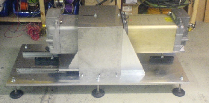
That’s not true, we had a test-rig with two async motors and a battery. One motor was driving the other, which ran in neg. slip angle mode as generator. It recharged the battery the other motor used for driving. Without the recuperation, the battery would have been empty very quick (200kW peak power), but it lasted 4 times longer.
One thing I’ve wanted to say, while reading the other thread was:
Have you seen how a 12V ignition-coil/ sparkplug system works?
The coil produces a high voltage when the magnetfield collapses. That’s exactly what happens, when we PWM the lower FET’s: we produce a higher voltage than the BEMF ever was. (inbuild boost converter)
The second pic doesn’t add any value to the discussion, just revv’ing good old times…
I was looking for an example how to control a BLDC with step/dir interface.
So far I’m only using the commander. What other input options do I have (from MCU to MCU)
I was also concerned about the motor.velocity_limit in the angle control example.
Usually the printer controller does all the acceleration/deceleration stuff. Now adding another instance would mess up the print.
What’s the default value? is it always enabled?
Can I configure simpleFOC to follow step signals instantly?
THX again
Olaf
Hey Olaf,
Other than commander we have the StepDirListener, which you‘ve already found. In our drivers library (separate library) we also have a SpeedDirListener for STM32 MCUs and an I2CCommander for control via I2C.
Also, several people are using @Grizzly‘s SimpleCAN library. Personally I’ve also used OSC via UDP on ESP32 MCUs.
So there are different options for control, and we do provide some building blocks and examples, but in the end this is application specific.
The velocity limit is always enabled, but you can just set it to a high value if you don‘t want to use it. I’m not so sure that’s a good idea, but it would be possible.
The StepDirListener is quite simple really, it’s intended to be used with position mode, and essentially outputs it’s current count value scaled by a user-defined scaling factor. It’s based on interrupts, so it will fairly quickly update its internal count, and the position target of the motor would get updated on the next call to motor.move()
Depending on your MCU and the setting motor.motion_downsample this would happen within a few milliseconds. After this the motor would move to the new position according to the electrical characteristics and PID settings. How long this takes is also dependent on the load.
Sorry, if I mislead you, I haven’t found any other example than those using commander.
How do I init stepDirListener?
//edit
Sorry, now that I know what to search for I found the docs…
There’s also an example:
In RRF 3D printer firmware the user can set timings for external stepper drivers. These are:
Minimum driver step pulse width,
step pulse interval,
direction setup time and
direction hold time,
The default value is 2.5ms for each of the parameters.
Does anyone see a problem with these timings for ESP32 step/dir interface?
Have a nice sunday
Olaf