It would be interesting to make a 12V only version that dropped the switching power supply circuit, and used smaller dual FETs instead of individual ones. Not sure how much cheaper that would be.
I’m breaking out as many spare I/O as I have to headers for communications and encoders, though there’s not a lot extra available! I was just asked by my business partner to add more analog to support a few thermistors so that uses even more I/O. But these things can always be deleted so more I/O is broken out to headers.
While possible, it would not really add value, and only create problems. LDOs are notoriously lossy, and you will end up solving nasty heat problems.
There are plenty of LCSC/JLC in-stock 1/2-bridge FETs. Some are up to 30V/30A. rather good prices, too, and not Chinese, either. I’ve designed a few boards with those in the past, they work. Some go to 40V but the current is obviously lower. There are some Chinese with higher specs, however, I do not believe even half of that they say.
Be careful however, some of the 1/2 bridge integrated do not have the diodes incorporated, if you like them you need to add explicitly the diodes, like the TI’s C140356 for example.
The SINO-IC C238670 looks perhaps a good candidate for you, but I’ve never done anything with it. Maybe you could try out and let us know. It’s a fully integrated 1/2 bridge. But then again, it’s Chinese.
If you are really into integrated components, there are quite a few threads here, we extensively experimented in the past with various integrated driver MOSFETs and IGBT modules. Search for IGBT or BTN and you will not be disappointed. I’m on vacation, cannot post any pics from my stuff but I think we posted all the schematics, etc. on those threads. Good luck with your projects and please post back your experience. Some of my boards are also public domain, over at oshwlab.com. Search for user Valentine (look for the bald bearded photo), go wild. There are also other users on this board with a plethora of both experimental and professional boards. But we are hijacking this thread, let’s head out.
I’m very curious to see how the RPi2040 MCU works in a custom project.
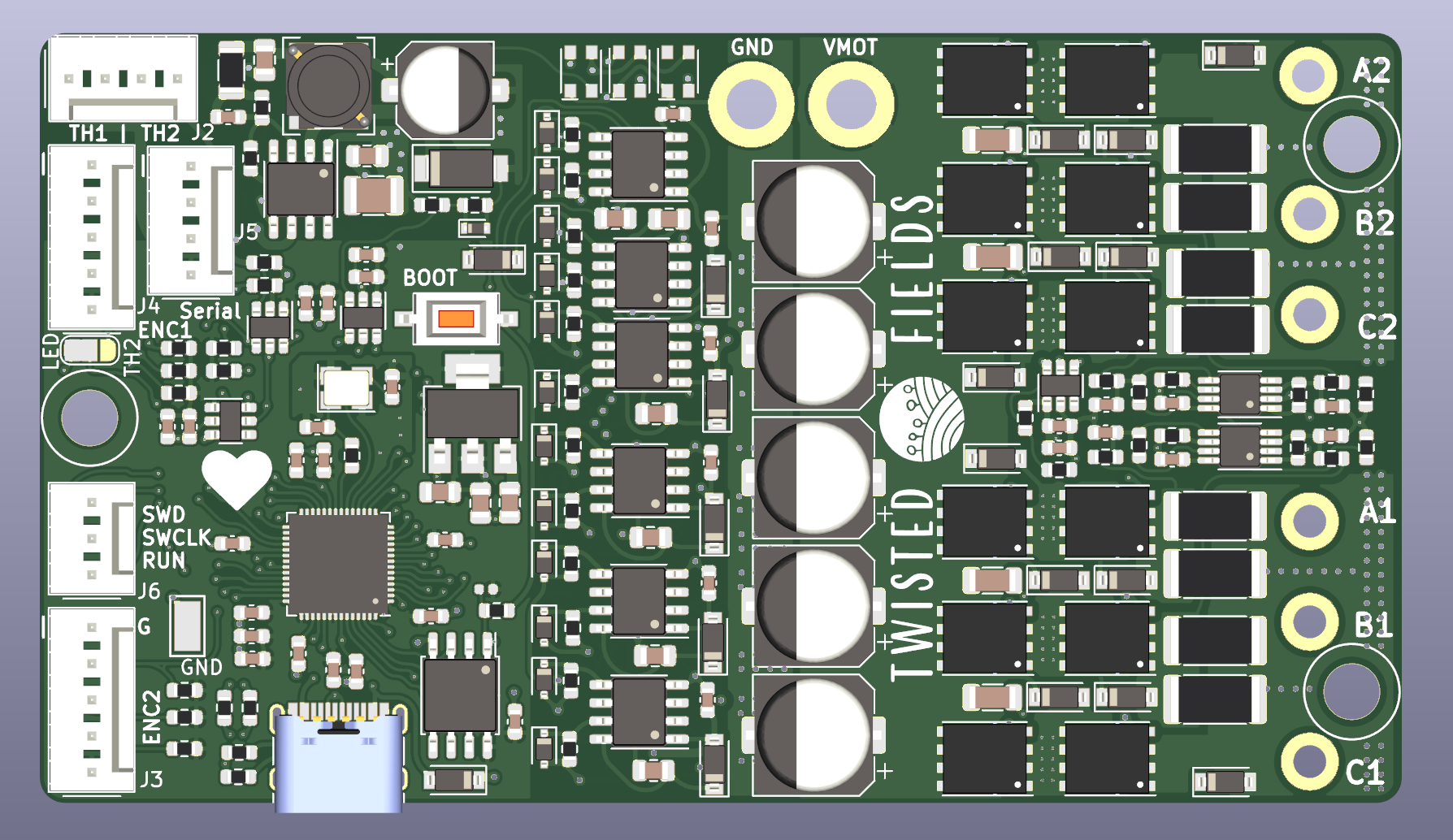
Hello everyone! So I finished the layout after a few rounds of design review with my team and with twitter users and feedback from here. I have ordered 10 boards from JLCPCB which will be finished in the next week and shipped DHL. So I will have them back within two weeks.
I made the board 10mm longer to add mounting holes and more copper area. I added a thermistor between the two bridges and two external thermistor ports. Both the 24V power in and the phase legs are on two layers for more copper area (GND is single layer but more area). I have also designed an encoder using the MT6701 chip which plugs in to the board’s encoder inputs with a straight through cable in I2C mode, though the encoder can also be jumpered for SPI mode. I ordered 20 encoder boards to play with.
We will have a limited number of boards in our first run, but I want to ask if there are any firmware devs who would like to help with bringup on this board who have the time and skills to do so, we would like to offer to send out a little dev unit for them to test. I will mount an encoder and a motor on a 3D printed stand all hooked up to the controller, so they can just power it on and work on firmware. I wanted to tag in @runger who seems to have done most of the RP2040 port and offer up a dev system. And if anyone else has the time and availability to help please let me know. (You can keep the system)
Thanks!
Here is the github link (posted before but sharing here for ease of click):
I’m limited to one media item per post as a new user, but here is the encoder board. This hole pattern matches the pattern on the back of some motors so in that case it can be directly mounted to the motor through a support plate. Photo of that here:
Hey guys, this looks like great work! Sorry for the slow response but I’m currently on vacation, enjoying some sunshine and time off work! Greetz from Teneriffa
I would be very happy to help with driver/firmware development, and help to test the board as much as my time allows… esp on the software side I think I can find enough time to be helpful, that’s generally more my expertise as well
I’m trying to use RPI2040 to implement SimpleFOC. Looking at the code you use for your board, I can’t find the implementation for the magnetic sensor MagneticSensorMT6701SSI. Is there any site where it is available?
The code for that is in our drivers repo, but on the dev branch:
It will be in the next release of the drivers, then it will work from the normal library, but for the moment you have to pull the dev branch.
And you then also have to use the dev branch of SimpleFOC also.