Reading the last bit of that thread, the response to your question, I think both is possible -
For method #2, we have a StepDirListener, which you could easily adapt the logic of, to effect control directly from the “pulse queue”.
For method #1, it is more interesting I think to send positions or velocities to SimpleFOC, and control it that way. I think this would be the nicer way to work, with more possibilities for improvements.
Does Klipper then have a closed control loop, or is it open-loop?
I think the fundamentally interesting part is at this level - how does Klipper determine the paths in the first place, and can it correct for errors? Things like this.
Klipper is bound by the Gcode, that´s what it want to achieve and it need it drivers to deliver on what it wants to execute. The SimpleFOC part would still be closed loop, because we track the movement of the shaft. If there is something wrong, like if the machine axis crash into something, SimpleFOC would know almost immediately.
The really interesting moment comes when the motor meets the metal, so to say. When the tool engages with the material, the torque-need for overcoming the much denser inertia will alter the control loop, possibly distort the velocity loop, so the driver has to catch up within a few iterations.
Here it is good to discern between the two main Gcode move types G0/G1 travel move and high torque move. In the CNC case we can assume that the high torque move need a minimum of torque to overcome the inertia into the material. Of course travel moves are much faster and without high inertia, so the torque need is different.
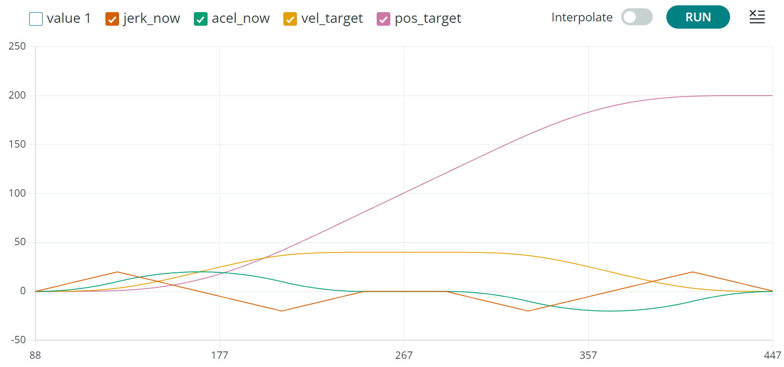
Move.set_junction() implements the “trapezoid generator” on a move. The “trapezoid generator” breaks every move into three parts: a constant acceleration phase, followed by a constant velocity phase, followed by a constant deceleration phase. Every move contains these three phases in this order, but some phases may be of zero duration.
When ToolHead._process_moves() is called, everything about the move is known - its start location, its end location, its acceleration, its start/cruising/end velocity, and distance traveled during acceleration/cruising/deceleration. All the information is stored in the Move() class and is in cartesian space in units of millimeters and seconds.
I think the best planner algorithm for your needs is MPC. But it is very computationally expensive and would not run on a microcontroller.
All PID and variations of PID are reactive controllers that react to error, but MPC is predictive. They call it “Model Predictive Control”. It uses a physics model of the overall system. First, you need to write this. It needs to predict position, speed and acceleration given an input. Then you need to write a “cost fuction” that assigns low cost to the desired behavior and high cost to deviation. It should reflect your real world use case.
You give the MPC algorithm a time horizon, say 2 seconds, and then you search for a sequence of inputs that will give the lowest integrated cost 2 seconds from now. You need an optimizer to find the best sequence of steps. Then you do at the curreny time step what leads to the lowest cost in 2 seconds. Then in the next time step, you start over from scratch. You might search through thousands of plans each time step and the steps might be 100 per second. So you might need to run the physics model 100,000 times per second.
These MPCs work also when there are many controls. I did one as a class exercise to parallel park a car where the controls were steering input and forward and reverse speed. It found a series of steering and velocity inputs to park the car.
Given enough compute power and a good physics model the algorithm will find the best solution and error does not accumulate because it starts over at each time step.
This is a good article
You might think MPC might be overkill for a motor speed controler but I bet the motor is part of a larger system and it is the system behavior that you really want to control. Perhaps the motor is driving a pick and place robot. So you model the robot and the cost funtion is the griper location and then this drives the voltage in the motor.
Klipper runs on a laptop or stationary PC running Linux. It has quite a lot of computational power. It assign each move with a timestamp. All MCUs are synced to the HOST. So in a sense it predict quite a lot of moves into the “motor_future”. Those moves a given in advance, which means we can prepare the FOC algorithm. But yes, that will take some system_clocks to do.
The trapezoid acceleration limiter ONLY actually does its job in the case of “trivial kinematics”. This is where rotational acceleration is proportional to linear acceleration. and (2) is independent of the position and acceleration of any other axis. This is the case with a 3D printer that has 3 axis that are all mutually perpendicular. The X-axis has no effect on the dynamics of the Y-axis. Most printers and milling machines use trivial kinematics
It is a MUCH harder problem once you get away from 3 mutually perpendicular axis. For example a human holding a 20 pound weight in one hand. The force on the shoulder joint depends on both the angle of the elbow joint and the shoulder. With trivial kinematics acceleration id proportional to torque. This is not always the case.
In the general case the motion planner must know the angles of all the motor before it can calculate the torque that will give a specified acceleration. So the planner can not live inside a motor controller except in the special case of mutually perpendicular axis
Looking the other way, this is why s many machine use trivial kinematics – bcause it make control so easy.
Mkay, so are you saying you want a RPi as a “node-cortex/main frame” kinda like a brain with wires instead of nerves ?
You could test your robot attached with a wire harness and then go fully autonomous when it’s matured.
I believe Klipper, in this case, will need feedback from each motor controller like when you (your brain/nerve impulses) feel the strain on your elbow while moving the object which makes you decide whether or not to apply more torque.
Another route would be to network the nodes with eg. CAN and have a de-centralized brain. I think you will need a co-processor on each motor-controller to achieve that without disturbing the FOC loop too much.
I know that this post is a bit old, however i was wondering if feedforward has been included in simplefoc?
it would appear that implementing may not be too hard.
The feedforward signal would be based on the acceleration rate of the commanded speed x feedforward gain. This signal is then summed after the velocity pid controller and finally becomes a current signal (or voltage) to the PWM generator.
commonly we would test a acceleration at a defined rate and look at the current required to maintain that rate. Then the gain would be calculated to produce that additional current, which is then summed with the pid output.
in essence, the feedforward addition is to aid the PID to follow a acceleration without needing the PID to integrate to the additional current for that acceleration. It is predicting the needed acceleration current based on the rate.
This is helpful to gain stability during the accelerations and additionally to minimize overshoot once reaching the desired velocity. If feedforward isn’t used, the integrated current to maintain the acceleration rate causes overshoot.