Heres something that might concern ![]() :
:
https://www.monolithicpower.com/understanding-the-magalpha-digital-filter
Not yet, i tried on the stm32, but i had some strange stuff. I switched to esp32 NodeMCU and tried lowside current. But I think I have other issues that I need to resolve before using current sensing.
The motor does not run at the same speed in both directions. Max speed consumes less current. When I reboot the microcontroller, the direction of the maximum speed can be reversed. And the current more or less.
Example:
Reboot
clockwise direction : 400mA (laboratory power supply)
counterclockwise direction : 400mA
The speed seems equal
Reboot
clockwise direction : 180mA (the fastest)
counterclockwise direction : 800mA
the speed is very different
Reboot
clockwise direction : 700mA
counterclockwise direction : 190mA (the fastest)
the speed is very different
I tried to reverse two bldc wires, same problem.
My bldc is wired in Wye, we agree that it works with simplefoc?
the code I use:
/**
* ESP32 position motion control example with magnetic sensor
*/
//ESP32 NodeMCU-32S
#include <SimpleFOC.h>
#define INH_A 25
#define INH_B 26
#define INH_C 27
#define EN_GATE 17
#define M_PWM 21//25
#define M_OC 16//26
#define OC_ADJ 12
#define OC_GAIN 14
#define CS 5
MagneticSensorSPI sensor = MagneticSensorSPI(AS5147_SPI, CS); //AS5048 sensor
// Motor instance
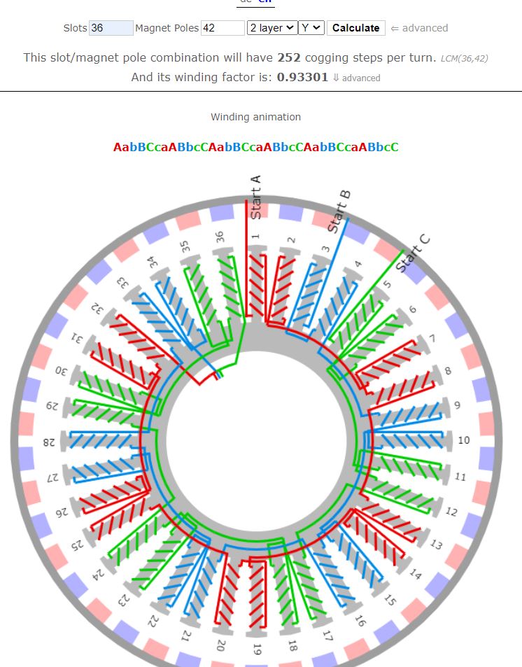
BLDCMotor motor = BLDCMotor(21); //42 Magnets and 36 coils
BLDCDriver3PWM driver = BLDCDriver3PWM(INH_A, INH_B, INH_C, EN_GATE);
// angle set point variable
float target_angle = 0;
// instantiate the commander
Commander command = Commander(Serial);
//void doTarget(char* cmd) { command.scalar(&target_angle, cmd); }
void onMotor(char* cmd){ command.motor(&motor, cmd); }
void setup() {
// initialise magnetic sensor hardware
sensor.init();
// link the motor to the sensor
motor.linkSensor(&sensor);
// DRV8302 specific code
// M_OC - enable overcurrent protection
pinMode(M_OC,OUTPUT);
digitalWrite(M_OC,LOW);
// M_PWM - enable 3pwm mode
pinMode(M_PWM,OUTPUT);
digitalWrite(M_PWM,HIGH);
// OD_ADJ - set the maximum overcurrent limit possible
// Better option would be to use voltage divisor to set exact value
pinMode(OC_ADJ,OUTPUT);
digitalWrite(OC_ADJ,HIGH);
pinMode(OC_GAIN,OUTPUT);
digitalWrite(OC_GAIN,LOW);
// driver config
// power supply voltage [V]
driver.voltage_power_supply = 31;
driver.init();
// link the motor and the driver
motor.linkDriver(&driver);
motor.voltage_sensor_align = 5; //i try several value, same issu
// choose FOC modulation (optional)
motor.foc_modulation = FOCModulationType::SpaceVectorPWM;
// set motion control loop to be used
motor.controller = MotionControlType::angle;
// contoller configuration
// default parameters in defaults.h
// velocity PI controller parameters
motor.PID_velocity.P = 0.2f;
motor.PID_velocity.I = 20;
// maximal voltage to be set to the motor
motor.voltage_limit = 8;
// velocity low pass filtering time constant
// the lower the less filtered
motor.LPF_velocity.Tf = 0.01f;
// angle P controller
motor.P_angle.P = 20;
// maximal velocity of the position control
motor.velocity_limit =100;
// use monitoring with serial
Serial.begin(115200);
// comment out if not needed
motor.useMonitoring(Serial);
// initialize motor
motor.init();
// align sensor and start FOC
motor.initFOC();
// add target command T
command.add('A', onMotor, "motor");
Serial.println(F("Motor ready."));
_delay(1000);
}
void loop() {
motor.loopFOC();
motor.move();
// motor.monitor();
command.run();
}
That is not a problem. SimpleFOC doesn’t care about the type of winding.
The way you describe it, I would assume the problem is that electrical zero is not found precisely. Especially the fact that it happens sometimes one way sometimes the other between reboots, with no other changes to the system.
I had a very similar effect in one of my setups, and it was due to too much load during alignment - too much friction, or just too much load meant the init routine just wasn’t bringing the motor into the right position.
You can try:
- increasing the voltage_limit during alignment
- If the setup allows it, do run the alignment with the load removed (as much of the cycloid disassembled as possible) and store the values. Then assemble and use the stored values (call motor.initFOC(offset, dir) with parameters).
- more lubrication?
May I ask where is your magnet for the sensor? Is it directly connected to the rotor, or at another point in the system?
The reason I ask is that a “loose magnet” could lead to similar problems too. But looking at the quality of what you’ve done, I don’t assume that’s your problem…
Is the magnet the correct kind, and of good quality?
I tried to increase the alignement voltage, still the same issu
All my try now is without Cycloid.
There is no friction, just two ball bearings and the magnets.
I also tried with a commercial bldc but with a homemade winding, a little different from my prototype (8318, 36N40P)and a 8mm magnet sensor, same issu
I would make you pictures of the magnet
When i display the angle with serialprint i get this (without loopFOC):
4,1786
4,1786
4,1786
4,1797
4,1782
4,1786
4,1797
4,1786
4,1786
4,1793
4,1789
4,1789
4,1793
4,1793
4,1793
4,1786
4,1789
4,1789
4,1793
4,1789
4,1782
4,1786
4,1789
4,1793
4,1793
4,1789
4,1797
4,1801
4,1786
4,1793
4,1801
4,1793
4,1789
4,1789
4,1786
4,1793
4,1786
4,1786
4,1797
4,1789
4,1797
4,1797
4,1789
4,1782
4,1786
4,1782
4,1786
4,1786
4,1789
4,1793
4,1786
When I looked at you motor I wondered how the stator was constructed. Somehow it looks like all the coils are separate units and that is not the way to do it. The stator should be a closed magnetic circuit or else there will be huge losses from eddy-currents.
This youtuber knows how to do it, maybe she will be kind enough to look at your problem :
https://www.youtube.com/watch?v=OZvjfbpXpro
( The interesting part starts at 5:02 )
I am using this king of stator: Moteur de Drone Stator sans balais, pièces de moteur de Drone, couple/puissance/vitesse élevés, Protection de l’usine UAV, accessoires de moteur, 8110 | AliExpress
And this winding
bavaria-direct.co.za
Ok, your error is about 1/1000rad, that is the same kind of value I get here on an MA730 sensor, and also what I would expect for a AS5048A or AS5047. 1/1000rad is 0.057° - the AS5147 gives it’s error (at 1700rpm) of 0.02°… so I would say this is ok, and sufficiently precise for driving a BLDC.
If you say you have the same effect with a different motor, then I am really wondering what’s happening…
I assume you were using the same MCU, sensor and magnet with the other motor? Which MCU was this on, the STM32 or ESP32?
Some news
I changed the magnet for a bigger one and check that I had between 30 and 70mT. The problem is not the magnetic encoder, because as you said, the measurement errors matches to the sensor resolution.
I solved the zero electric issu which cannot be detected automatically. It is really not elegant but my method is as follows :
- I am looking for the electric zero approximately with the initfoc and I try to turn the motor in both directions and I look at the current consumption. In 95% of cases, the current is different and the speed too.
- by trial and error, I slightly change the zero electric in intfoc (zero electric, direction) and I check the current
- when the current is the same in both directions, I keep the zero electric
I am a little disappointed not to have understood where is the problem but maybe I would understand later.
Thanks for helping me
same issu on STM32 F091RC and blackpill F411CE and ESP32 nodemcu 38pins
Low-side current sense and foc_current control on stm32 Blackpil seems to work with this code (adjut zero electric according to your setup)
#include <SimpleFOC.h>

// DRV8302 pins connections
// don't forget to connect the common ground pin

#define INH_A PA10
#define INH_B PA9
#define INH_C PA8


#define EN_GATE PB9
#define M_PWM PB8
#define M_OC PB7
#define OC_ADJ PB6
#define OC_GAIN PB5

#define IOUTA PA1
#define IOUTB PA2
#define IOUTC PA3

#define nCS_PIN PB2


// Motor instance
BLDCMotor motor = BLDCMotor(21);
BLDCDriver3PWM driver = BLDCDriver3PWM(INH_A, INH_B, INH_C, EN_GATE);
//BLDCDriver6PWM driver = BLDCDriver6PWM(INH_A,INL_A, INH_B,INL_B, INH_C,INL_C, EN_GATE);

// DRV8302 board has 0.005Ohm shunt resistors and the gain of 12.22 V/V
LowsideCurrentSense cs = LowsideCurrentSense(0.005, 12.22, IOUTA, IOUTB,IOUTC);

// encoder instance
MagneticSensorSPI encoder = MagneticSensorSPI(AS5147_SPI, nCS_PIN); //it s a AS5048but it swork with AS5147_SPI


// commander interface
Commander command = Commander(Serial);
void onMotor(char* cmd){ command.motor(&motor, cmd); }

void setup() {

  // initialize encoder sensor hardware
  encoder.init();
  // link the motor to the sensor
  motor.linkSensor(&encoder);

  // DRV8302 specific code
  // M_OC  - enable overcurrent protection
  pinMode(M_OC,OUTPUT);
  digitalWrite(M_OC,LOW);

  //PWM MODE
  pinMode(M_PWM,OUTPUT);
   // M_PWM  - disable 3pwm mode
  //digitalWrite(M_PWM, LOW);
  // M_PWM  - enable 3pwm mode
  digitalWrite(M_PWM,HIGH);

  // OD_ADJ - set the maximum overcurrent limit possible
  // Better option would be to use voltage divisor to set exact value
  pinMode(OC_ADJ,OUTPUT);
  digitalWrite(OC_ADJ,HIGH);

  pinMode(OC_GAIN,OUTPUT);
  digitalWrite(OC_GAIN,LOW);


  // driver config
  // power supply voltage [V]
  driver.voltage_power_supply = 31;
  driver.pwm_frequency = 50000;
  //driver.dead_zone = 0.02;
  driver.init();

  // link the motor and the driver
  motor.linkDriver(&driver);
  //motor.voltage_sensor_align = 5;


  // control loop type and torque mode
  //motor.foc_modulation = FOCModulationType::SpaceVectorPWM;
  motor.torque_controller = TorqueControlType::foc_current;
  //motor.torque_controller = TorqueControlType::voltage;
  motor.controller = MotionControlType::torque; //to avoid hasardous movement then a switch on MotionControlType::angle
  //motor.controller = MotionControlType::angle;

  // velocity loop PID
  motor.PID_velocity.P = 0.2;
  motor.PID_velocity.I = 5.0;
  // Low pass filtering time constant
  motor.LPF_velocity.Tf = 0.01;
  // angle loop PID
  motor.P_angle.P = 30.0;
  // Low pass filtering time constant
  motor.LPF_angle.Tf = 0.0;


 // current q loop PID
  motor.PID_current_q.P = 1; //3
  motor.PID_current_q.I = 50.0; //300
  // Low pass filtering time constant
  motor.LPF_current_q.Tf = 0.01;
  // current d loop PID
  motor.PID_current_d.P = 1; //3
  motor.PID_current_d.I = 50.0; //300
  // Low pass filtering time constant
  motor.LPF_current_d.Tf = 0.01;

  // Limits
  motor.velocity_limit = 100.0; // 100 rad/s velocity limit
  //motor.voltage_limit = 5.0;
  motor.current_limit = 5;


  // use monitoring with serial for motor init
  // monitoring port
  Serial.begin(115200);
  // comment out if not needed
  motor.useMonitoring(Serial);
  //motor.monitor_downsample = 100; // set downsampling can be even more > 100
  //motor.monitor_variables = _MON_CURR_Q | _MON_CURR_D; // set monitoring of d and q currents


  // driver 8302 has inverted gains on all channels

  cs.gain_a *=-1;
  cs.gain_b *=-1;
  cs.gain_c *=-1;

  cs.init();
  cs.skip_align = true;
  motor.linkCurrentSense(&cs);

  // initialise motor
  motor.init();
  motor.initFOC(3.7, Direction::CW); //3.61
  //motor.initFOC();

  // set the inital target value
  motor.target = 0;

  // define the motor id
  command.add('A', onMotor, "motor");

  _delay(1000);
}


void loop() {
  // iterative setting FOC phase voltage
  motor.loopFOC();

  // iterative function setting the outter loop target
  motor.move();

  //motor.monitor();

  // user communication
  command.run();
}
I must say, I’m disappointed too. I really wonder what’s up. If the motor works well after you find the zero-angle using your “extended” method, then it means the problem occurs at init-time, and not afterwards, so it is unlikely to be a slipping magnet or other physical problem.
And the fact you have the same problem with different MCUs and different motors, means it is a software, driver or sensor problem, but not the motor.
One thing I note is that the voltage_sensor_align and voltage_limit are quite low compared to the voltage_power_supply. Why run it at 31V if you’re only using 8V? You will have a better fidelity on the PWM output if you bring these values closer together… But somehow I doubt that’s the source of the problem.