Hi @DomenicoGiampetruzzi, glad you like my projects
I’m also not a robotics expert and I totally understand what you’re saying and I agree. My Matlab model not only included the kinematics model of the robot, but it followed a S like curve for the positioning of the end-effector taking into account the desired start and stop speeds and the maximum acceleration allowed. At the end I just have an array of angular positions for my actuators and a sample rate, if I follow the planed angular positions at the calculated rate all the benefits of doing an S curve motion plan will be achieved. This is why I think it’s outside the job of the controller.
I have also been experimenting with these kinds of motors, and some applications such as low noise fans and camera gimbals really do need non-cogging motors. I am not clear exactly how these motors work, but apparently it is actually possible to make a motor that is fully non-cogging, or apparently close enough. I got some 32 mm gimbal motors once that were apparently fully non-cogging, they gave smooth and almost silent motion. Also when you turned them by hand there was no noticeable cogging. However I was not able to get more of them :(. Thus I cannot use them in my OpenERV project. I got some that are relatively similar.
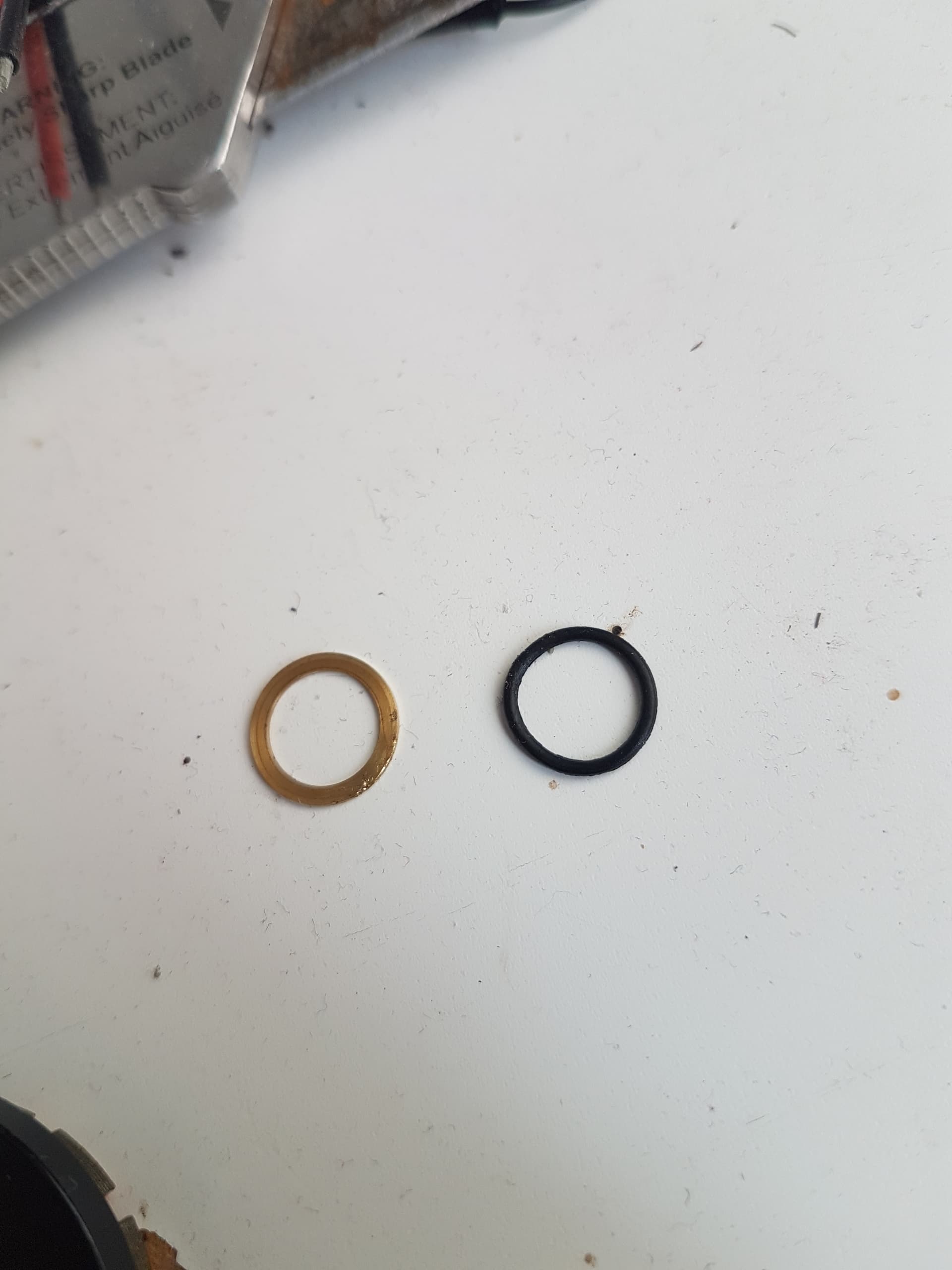
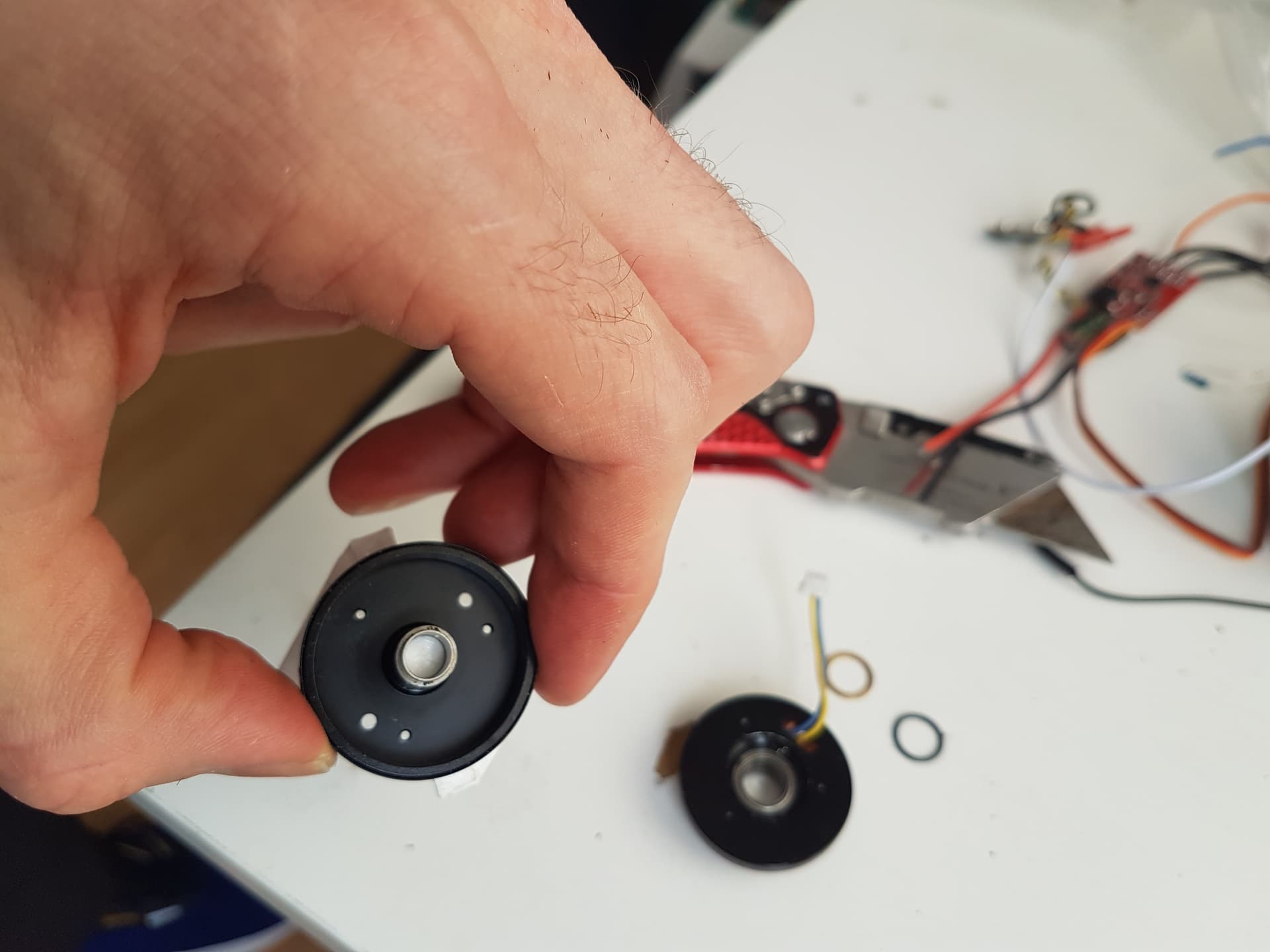
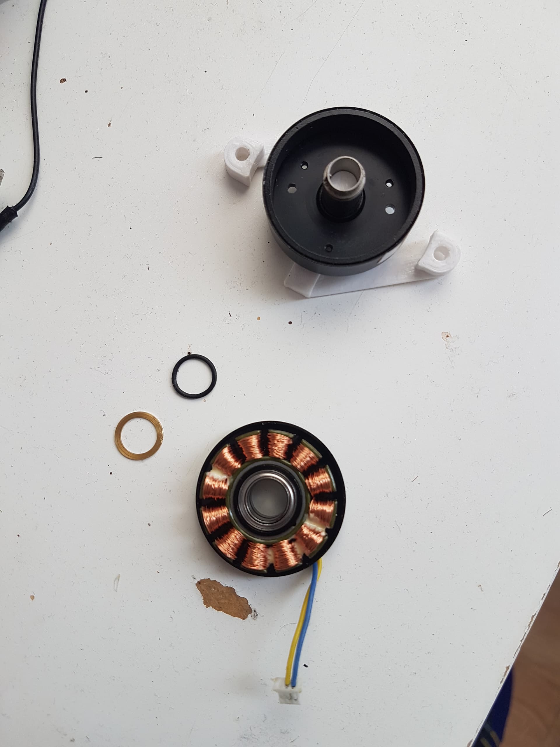
I dismantled one that I had broken by accident, and a major difference I noticed is that they use a ring of ceramic, probably similar to ferrite, as the permanent magnet, so there are not gaps between the magnets, and the faces of the magnets are circular. All other motors I have encountered use discrete rectangular magnets arranged in a circle, but each one has a flat face. I don’t know what exactly they are doing in either case, but I can see this may be part of the problem, as that would lead to a less than ideal magnetic field distribution and things.
I don’t know how you could make a decent camera gimbal with a cogging motor, I suppose they depend on the sensor to counteract the cogging. It still wouldn’t help.
When I advertised on alibaba asking for a non-cogging motor I got a few replies but they kind of wanted a lot of money and these guys just make stuff up sometimes, they might have sent me a motor that was actually pretty coggy, who knows.
You can reduce cogging torque by physically skewing the motor stator poles, or by skewing the rotor magnets. The latter is done in commerical AC servo motors (Fanuc, etc.). Take a look here: BuildIts in Progress: Desktop Inverted Pendulum, Part 1
Was it maybe the difference between a PMSM (sinusoidal BEMF) and BLDC (trapezoidal BEMF) motor?
Is the ceramic perhaps just an enclosure for individual magnets inside? I don’t suppose you have a datasheet or product link or anything? I’d be interested to see…
Maybe. The ceramic was definitely not an enclosure, it was solid magnetic material. I can pull it out and take pictures, but unfortunately as with many of these cheap chinese components, there appears to be no datasheet or part number of any kind. The part was from ali express and has since been sold out and the product listing is gone, but it appeared nearly identical on the outside to any other 32-34 mm brushless gimbal motor with 360 degree unlimited rotation (you have to watch out, some are limited and can’t turn continously, I got one like that once, it just had a useless metal peg that prevented it from turning, I was able to remove it but it was laborious and damaged the motor slightly so not suitable for making products from).
Huh, maybe someone who knows more about it can comment…
It apparently isn’t easy to find in a web search without knowing the term to look for…
As far as I can tell ferrites are inferior to the rare earth type magnets for motors, as they aren’t as powerful and they can demagnetise more easily. But maybe in certain applications they’re preferred?
Cogging is determined by mechanical properties, it can be eliminated by not having gaps between the core where the wire is wound, this can be done in multiple ways, for example by skewing the layers in the core as mentioned by @wrcman555. This also have the advantage of having a smoother transition between the poles (simular effect as helical gears). Also the gaps between the magnets is a determining factor.
If I remember correctly, there is some information about this topic in the book brushless permanent motor design (you can find a pdf online).
These guys discuss an algorithm to compensate for cogging in software using the encoder, giving much smoother motion with cheap motors, I think this would be a really good feature to have in SimpleFOC. I searched on google scholar, and there are several others that discuss similar stuff. Anti-Cogging Algorithm Brings Out The Best In Your Hobby Brushless Motors | Hackaday
It would increase the value of the motor system substantially, improve performance, and it doesn’t cost any hardware, so it seems like just the thing to do.
Hi… did u use the 5010 360kv motor with SimpleFOC shield arduino board? Do u know if I can use that motor? The motor has an electrical resistance of 1 Ohm… Normally the gimbal motors have 10 Ohm or more… Thank you
You can limit the de facto maximal voltage but you definitely have to be careful. It almost fried my motor with some pie loop oscillations when the voltage was set to 6 v In software but was 12 volts from the power supply. I’m starting to thing this board may not be suitable.
Yeah, those motors can no longer be obtained, I read about them several times. They had very low cogging, and were only a couple bucks but for some reason they stopped making them and now they are all sold out.
It appears to be well made, there are other motors I have similarly dismantled that have bearings that fit too tightly and thus make noise (the balls are apparently being compressed or have no cage). This one even has a nice oring o the the back to keep everything firmly together without causing excessive stress. There is really no discernable cogging. I do not know how they do it as as you can see there are gaps between the poles. There is only two wires in the pic because I broke one off by accident, they are a little less than ideal in that department. I would definitely use these if I could get more. There is a circlip on the shaft that is missing, I removed it and didn’t bother keeping it as the motor is broken.
Carel:
This is good stuff and thanks for it, but it’s important to realize to actually get stuff done we have to actually have such a motor. The hope of implmenting anti cogging in simplfoc is that widely available motors can be used and still get a good result, these kinds of low and anti cogging motors are very uncommon and usually very very expensive.
these guys are doing what I was thinking of, they are compensating the waveform, they also tried using a PID loop and even combining the two, to apparently get a 75% reduction in cogging torque ripple, pretty good for some software. I’m sure it’s not trivial to make it happen, but once it’s done everyone in the world benefits forever more, getting a better result with exactly the same hardware. Cogging compensation in embedded brushless motor control for haptics applications | Semantic Scholar
Get the full doc on sci-hub.
Here is another project that would benefit from anti-cogging, I don’t know if they know about simplefoc or what driver they are trying to use right now. That’s a low speed application so I would expect they could compensate for cogging using a pid controller, however they seem to indicate they are having a hard time doing so.GitHub - scottbez1/smartknob: Haptic input knob with software-defined endstops and virtual detents
Yes ofcourse you can compensate this with software, there are two main methods, but they come down to the same thing, you need to make a map of the cogging and superpose the inverse to the driving torque. I was just explaining where it comes from. This video shows both methods:
There are a few other motor drivers that implement something like this, ODrive, Tinymovr, …
Take a look in the Discord group at the anticogging section, there are useful links.
A little bit of background. I come from automotive, where we are developing inverters for PMSM and ASM based powertrains.
Lets leave ASM aside. For PMSM when using FOC with SVM, I can tell you that the single most difficult thing to achieve is the timing synchronicity between phase current values and rotor position. If you are off for only as much as 100us at high speed (5000RPM+), you will get noticable behaviour, it feels much similar to “cogging”.
What im trying to say, for FOC you need both, currents and position to be sampled at exactly the same time. Or at least corrected properly for the Park transformation. I am not saying SimpleFOC is not optimised. Quite the contrary, I see that even Sine / Cosine is reimplemented with look-up tables. Hats off
I would be curious to see the time it takes from getting the position, to calculating Id and Iq (see snippet below). One could hypothetically just toggle pin and attach osci to measure the time.
void BLDCMotor::loopFOC() {
  // update sensor - do this even in open-loop mode, as user may be switching between modes and we could lose track
  //                 of full rotations otherwise.
  if (sensor) sensor->update();

  // if open-loop do nothing
  if( controller==MotionControlType::angle_openloop || controller==MotionControlType::velocity_openloop ) return;

  // if disabled do nothing
  if(!enabled) return;

  // Needs the update() to be called first
  // This function will not have numerical issues because it uses Sensor::getMechanicalAngle()
  // which is in range 0-2PI
  electrical_angle = electricalAngle();  // <<< TIMEIT FROM HERE
  switch (torque_controller) {
    case TorqueControlType::voltage:
      // no need to do anything really
      break;
    case TorqueControlType::dc_current:
      if(!current_sense) return;
      // read overall current magnitude
      current.q = current_sense->getDCCurrent(electrical_angle);
      // filter the value values
      current.q = LPF_current_q(current.q);
      // calculate the phase voltage
      voltage.q = PID_current_q(current_sp - current.q);
      voltage.d = 0;
      break;
    case TorqueControlType::foc_current:
      if(!current_sense) return;
      // read dq currents
      current = current_sense->getFOCCurrents(electrical_angle);
      // filter values
      current.q = LPF_current_q(current.q);
      current.d = LPF_current_d(current.d);
      // calculate the phase voltages
      voltage.q = PID_current_q(current_sp - current.q);
      voltage.d = PID_current_d(-current.d);
      break;
    default:
      // no torque control selected
      SIMPLEFOC_DEBUG("MOT: no torque control selected!");
      break;
  }

  // set the phase voltage - FOC heart function :)
  setPhaseVoltage(voltage.q, voltage.d, electrical_angle);  // >>> TIMEIT TO HERE
}
Yes indeed! That’s often how I look at the timings, using the logic analyser…
We’re certainly not there yet… but we’ll get there.
It is very interesting for us to hear an experienced voice in this regard. It’s not that usual for our users to target 5000RPM or more, I don’t think, but we’re of course still eager to implement things correctly (while keeping them simple )
In low side sensing, the current sensing is synchronised to the PWM, so there is no optionality in that direction. With low side sensing it would mean synchronising the position sensing to the current sensing.
In inline sensing, I guess one would have either option.
This information, and generally the improved latency really points towards ABZ type position sensor being better for high speeds - the latency you get when polling sensors via SPI will be a problem for high speed control anyway, but very difficult to synchronise with the ADC.
With ABZ encoders implemented via hardware encoder support it should be possible to use events/interrupts/dma to get a super-tight synchronised ADC + encoder reading…
Something I will keep in mind, and hope to implement in the future…
No, actually the sensor is sampled by this line: if (sensor) sensor->update();
After this the sensor “holds” its value until the next time you call update.
Thank you, and please don’t hesitate to share any other ideas/observations
Hi @runger! I have came across this community only yesterday during lunch. But I stayed until the midnight. Processing the website and forums. I think I have fallen in love.
I happily admit, the work you guys did, the state of documentation, the modularity of SW, the community itself… it deserves nothing less than a big respect! Please carry on
I will try to contribute in any way (already bought a BLDC and B-G431B-ESC1 yesterday hehe). But I need to first adopt arduino style STM32 programming. I prefer the native STM32, I feel I have more control over uC behaviour.
But as some of you already stated in other posts, the goal of SimpleFOC is to be simple, modular and user friendly tool which can be used for majority of cool projects. And I think you are on the right track
I’m starting work on anti-cogging within SimpleFOC for low RPM’s only. My specific application is my home flight simulator, where I have a sliding handle that I want to simulate friction / force on as the lever extends speed brakes on an airplane. The motor is connected to the lever via a belt drive very much like a stepper motor controls an axis on a 3D printers. RPM is unlikely to ever exceed 100.
I think generally this would also apply to most force feedback joystick controls as well. As I begin my experiments, does anyone have any suggestions on the most likely path to success? Which method would you suggest I start with?
Sample often and use high holding torque.
calibrate and use a look up table to cancel error.
Something else?
I’ll be working with a very coggy 57BLF03 motor so that I can know whether or not I made improvements. For hardware I’ve got both a B-G431B-ESC1 and a Nucleo F446 with a standard PWM controlled BLDC driver. In all cases I plan to use either the AS5600, AS5047/5048, or TLE5012 (15bit resolution) position sensors via SPI. Of course all driven by SimpleFOC. Thanks for any advice.
-Jim
Well, I did some work on it to bridge some „waiting for components time“, with a very similar setup, but a very low cogging motor and I did not get anywhere with it. Since I do not need it with my motors, I stopped working on it when I could continue with my real project. I would recommend though to start with sensor calibration and put the anticogging on top. I can send you my calibration code later.