Changing PWM dead time or other parameters with B-G431B-ESC1 board

How do you change the freq. for STM there are actually two ways, which can lead to some confusion.

Here;

// default pwm parameters
#define _PWM_RESOLUTION 16 // 12bit
#define _PWM_RANGE 65535.0f // 2^12 -1 = 4095
#define _PWM_FREQUENCY 2000 // 25khz
#define _PWM_FREQUENCY_MAX 50000 // 50khz

And here:

pwm_frequency = NOT_SET;

I put driver.pwm_frequency = 25000; just before driver.init in the setup section of the code?

You may have to change these values not sure if this is the best implementation.

_setPwm(((STM32DriverParams*)params)->timers[2], ((STM32DriverParams*)params)->channels[2], _PWM_RANGE*dc_b, _PWM_RESOLUTION);

@runger

The confusion is a result of using this:

setOverflow((uint32_t)PWM_freq, HERTZ_FORMAT);

In order for it to have any meaning to change the Overflow, in HERTZ, you also has to change the

_PWM_RANGE*dc_b, _PWM_RESOLUTION

Edit: Never mind. I see it is quite complexā€¦

void HardwareTimer::setCaptureCompare(uint32_t channel, uint32_t compare, TimerCompareFormat_t format)
1 Like

That should workā€¦

The HAL interface to the timers is a bit complicated. I would actually prefer to do it a different way. If I understand correctly what HAL is doing we set the frequency in Hz and the desired resolution (fixed at 4095) and it sets the timer to produce this.
Iā€™d prefer to keep the timer frequency fixed, the PWM frequency as configured, and have the range vary, perhaps that will be a refactoring of the futureā€¦

2 Likes

The resistors were the wrong size, 10 ohm instead of 1 ohm, have to wait till tomorrow to get some more.

But this phenomenon is bizarre. With 150uH inductors followed by a 10uf capacitor, how can any such brief voltage or current transient sneak by unaffected? And yet adding them makes no audible difference. Itā€™s like magic. Maybe the ringing noise is somehow not coming from the electronic drive signal. And yet it is clearly a very steady, electronic sounding noise, and I donā€™t know what else could be causing a ringing noise of that nature.

I think I will try the texas intruments chip again and see if the noise arises with it. Or hey maybe it is actually emanating from the board itsself or something, I didnā€™t think of that.

Iā€™m curious why didnā€™t you then get the Mosquito, and get it over with. Itā€™s based off a cheap TI $2 commercial integrated 3PWM driver, really tiny, you can put G071 instead of G031, and you can stick a sensor on the back. Why are you even trying to make a discrete component board from scratch. At 0.3A current sensing is not even in play. You just need to spin a small fan quietly, right?

Because I didnā€™t know about the mosquito :(. That is the only reason. I looked at the recommended hardware, and it wasnā€™t there IIRC. I also thought that there were issues with 3 pin pwm, however I think I was probably wrong about that.

Update: I hypothesized that during the dead period when neither mosfet is conducting, the half h-bridges cannot allow any current to pass in either direction. This is a deviation from the ideal of the 3 phase ac current situation. I thing that whatā€™s happening is that the current cannot flow for a brief time then. I tried reducing the dead time but there must be practical limitations of some kind. Theoretically I suppose itā€™s possible to get it down to a microsecond or something, which would probably be fine, but I think the abstractions that are used when configuring the pwm peripheral settings etc. lead to deviations from that ideal, or perhaps there is some other issue that for practical reasons prevents that.

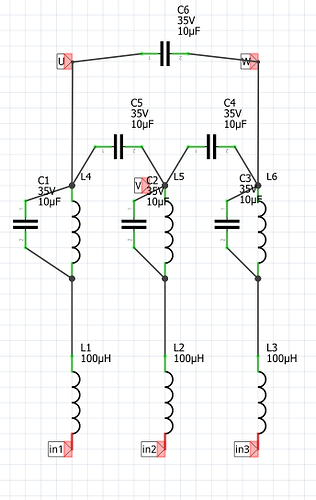
I connected some 100 uh inductors and 10uf ceramic capacitors in the way indicated below, it works :). The first set of inductors gets a bit warm at 150 rads per second, and it consumes considereably more current (about 70 percent more), but thatā€™s not a big deal.

I hope I can optimize the values of the components etc. to improve. Additional stages would allow for less wasted current I think.

Basically my hypothesis is that with only the first set of inductors and the capacitors between the output terminals, the interruption in current into the first inductors leads to a surge in voltage which leads to a surge in current when the mosfets become conducting again. This kick is not damped by the capacitors for some reason, but instead gets passed along.

The function the first stage inductors performs now is just to block the high frequency PWM frequencies. Without them, excessive current flows through the capacitors.

The second set of inductors and capacitors muffles the voltage kick, I think? I havenā€™t really inspected with my oscilloscope. Iā€™m sure the component values are ridiculous, and this may not be considered a great approach in many ways, but itā€™s a first step, and seems to validate my hypothesis about the problem being the dead spot.

in1, in2 and in3 got to the driver, the g431 board.

edit: realized I could get rid of about half those components, got rid of l1, l2 and l3 and the capacitors across the U, V and W terminals. It is very slightly louder but not much, and a lot less wasted current, and the l1 etc. inductors were getting a bit warm.
First of all: I am really no experts on filtering! However, what I believe you should do is to start with an equivalent circuit of the motor. This is a resistor and an inductivity in series per phase. These already form low passes, essentially, what you are looking for. The cut off frequency can be easily calculated. Should it be too high, you can extend the LP with additional components. My guts tell me that probably you will be fine with additional capacitors between the motor phases or three capacitors connected with one end to each other and the other end to one phase each. The problem I see however, is that the winding resistors are in the wrong place for a standard LRC filter, but maybe, the parasitic resistance is low enough to be ignored anyway. Maybe someone else has more expertise in analog filter design and can jump in here? In any case, I would really start with a formula including the motor inductivity to give you a rough idea of the dimensions you need.

How can you start designing a filter without knowing what frequencies you are trying to remove?
Itā€™s really important to understand what noise this is, if is purely electric or acoustic (bearings, etc) and the frequency before you can start designing this. Otherwise you will just go in circles. Putting big capacitors on can solve some problems but bandpass filtering is not one of those. The capacitance needs to be tuned to the frequency you are filtering.

1 Like

Especially if the noise is due to the motor frame warping from the flux force and magnifying the noise through the fan blades. No capacitor or any other electrical filter could fix that type of noise, only a complete motor/blade rotor redesign.

The noise is not due to such a powerful phenomenaā€¦ it is glitches in the waveform.

It works, lol, perhaps filter is the wrong word. I am merely smoothing.

The inductee and capacitor work together to prevent glitches in the current flow, apparently due to the period when the half h bridges are completely non conducting when they cross the zero voltage region.

With true 3 phase ac, current would still flow from one terminal out another when one terminal had zero volts. That canā€™t happen here though.

The capacitor allows current to continue to flow through the phases of the motor for a short time even when the mosfets are non conducting, thatā€™s my theory of whatā€™s happening.

The good news is it works fine :). It does seem to waste a bit of current/power somehow, but not much. In retrospect if I had thought of this before I might have been able to use it to silence the glitches of other origin, such as the once per rotation click or the 1khz hum caused by the i2c communication with the sensor. Sigh.

Well I got there in the end. Is it worth it? Idk. We will see.

2 Likes

19 posts were split to a new topic: PWM Deadtime compensation

The heating happens whether it is under load or not, i.e. it is affine, more or less. So it can actually handle considerable loads.

But yes we need a more suitable board, itā€™s just a matter of cooking one up, testing it, getting any bugs out etc. This was the purpose of the lepton 3.0 and part of the purpose of the lepton 2.0 and QUADVRANS (sp?). Just more stuff that needs doing basically, there is no really good generic board right now, this board is the closest for many purposes.

is anyone actually working on Lepton 3? I havenā€™t seen any discourse on the development, just talking about what it could be.

We had this discussion before and I still cannot confirm this. No load and the board stays relatively cool (except for the buck converter maybe). Pull some Amps from the phases and it gets hot. Small heatsinks on the MOSFETS and/or a small fan and it stays luke warm.

I have it slated for eventual doing when I start producing ventilators, but that could be a long long way away unfortunately. There is no other board that will work for me. The first stage is to look over the b-g431b-esc1 board and the Lepton 2.0 and QUADVRANS (sp) and my list of requireements/feature requests, and draft a combination board. Probably by modifying the lepton 2.0 schematic for current sensing and the g431 mcu and a few other things and then re-routing it. Unfortunately I am extremely bogged down right now and have been for some time and itā€™s not clear if I will actually be producing ventilators anyway so that sucksā€¦ Truthfully I should probably stop compulsively checking these forums, I think I am stretching my limited experience and remaining chips in the game a bit thin :P. However it is useful to accrue interested parties, and I have learned additional stuff about sensorless drive for instance which have been influencing the ideas I have for the lepton 3.0 constructively. Also I think we may have averted a problem with the voltage spikes caused by the ceramic capacitors due to lead/trace inductance, but thatā€™s not clear.

Thatā€™s what I was taking away from the thread on the subject, was it you who used a thermal camera or something? I used an infrared thermometer and from 100 mA to 2 A draw the heating didnā€™t change much, in any case it was in a workable range. Earlier posts by others such as Valentine indicate it does get too hot to handle itā€™s rated current without liquid cooling or extensive airflow, and possibly even with extensive airflow.

Clearly itā€™s not the end of the line, there is room for improvementā€¦