You can use the PIO stuff in the rp2040 to do interrupt free encoder reading. It’s just as you describe, but programmable. The state machine will count the pulses and update a register, then updates a fifo, you read the fifo and you are good. the state machine can also give an interrupt to the main cpu every whatever many pulses or something. Or you can request a reading and grab the latest position or whatever, very flexible and powerful.
It’s too bad they limited the pio program lenght to 32 instructions, or you could make something that output the pwm precursor to the sine wave automatically, you just tell it the frequency and amplitude. That would be nice and free a lot of cpu resources, oh well. There might be a way to do something like that but it would take some skill.
Have you written a hardware encoder on the PIO engine?
Sure, it’s possible, but it’s also quite a lot of extra work, when a driver for stm32 is already written…
Or we can add an FPGA to some simpleFOC boards for handling DDS PWM and encoder hardware
By the way, PWM peripherals already work like how you describe → you only control the frequency and amplitude, you are not bit-banging if you’re using the HW peripheral.
I only work at very low speeds, so what I am proposing may be total nonsense, but I would try it if I had to take SimpleFOC to the extremes: Use a tracking filter to compensate the electrical angle for the delay of sensor and code to maximize speed or reduce current. This dynamic compensation should only be active while the motor is at a reasonably steady state. Good filters here could be g-h filters with their tracking properties. If this gives an advantage over a linear lag compensation as proposed by @Anthony_Douglas - I don’t know, but it may help to adjust the linear fit.
I think the RP2040, at least the Pico, is clocked at 125MHz.
But I think changing MCU is a distraction. The G431 is an excellent MCU to work with, and changing to a Pico would not be faster, in my opinion.
To go faster than the G431 would need a faster STM32, a Teensy or a ESP32.
Sticking with the G431, I think using the STM32HWEncoder to have 0-overhead sensor readings would be the way to go. STM32HWEncoder(ppr, PB6, PB7, PB8); on the G431-ESC1 should do the trick, I think? These pins are all on TIM4 so should be able to use encoder mode of this timer.
So if you can get an AS5047P based sensor board to swap out your AS5048A you could get quite a speed-boost, I think…
I’ll try to find the CORDIC code for you this evening… have to search for it.
Thank you so much for all the replies, this is truly helpful !
I have ordered the new AS5047P sensors already, will try that when I get them. And in the meantime I will see what I can do with a linear offset, as suggested by @Anthony_Douglas.
And yes, if I could stick with the same board at least, that’d much easier. Thank you @runger, the CORDIC enhancement sounds like a very good thing to try out.
Would it be imaginable to stop using the sensor completely at higher speeds and instead rely on BEMF measurement or is this non-sense?
Oh, maybe I misunderstood. If the G431 is being used, just keep that! I saw in the top post that the Pico was the board being used here.
I definitely think the STM32HWEncoder is the way to go here.
It’s not nonsense, and the B-G431-ESC1 is set up for voltage measurements in terms of the hardware, IIRC.
But it’s not supported at all in our library at the moment… so in those terms it’s not a quick solution for you.
I believe the combination of ABZ Sensor used via HWEncoder and the CORDIC optimization may get you to your goal.
In the PM conversation @Candas1 mentioned in post #17, we were thinking of leveraging SmoothingSensor for this. Add a new variable to apply a fixed offset to the timestamp before calculating the predicted angle. To get good results, you’d have to measure the average time between the sensor update and PWM duty update on your specific hardware.
But if using hardware current sense, you’d ideally want to make two separate angle predictions, or perhaps use the previous frame’s angle for the current transformation. Otherwise you’ll be transforming the start-of-the-frame current readings by the end-of-the-frame angle, and cancel out your improvement. But I’m not sure how to cleanly integrate that into the library code.
I tried downsample rates of 22 on my ST32F030, but I didn’t notice any difference.
I also mentioned before, there is a typo in the default.h file (@runger )
I’ve tried to play with the motor.zero_electric_angle value to see whether this would help, as suggested above. And the difference is massive.
Not only do I reach speeds of 1700 rad/s (and possibly beyond), the currents are much lower at high speeds. Main loop is still around 13 kHz with the changes I reported here.
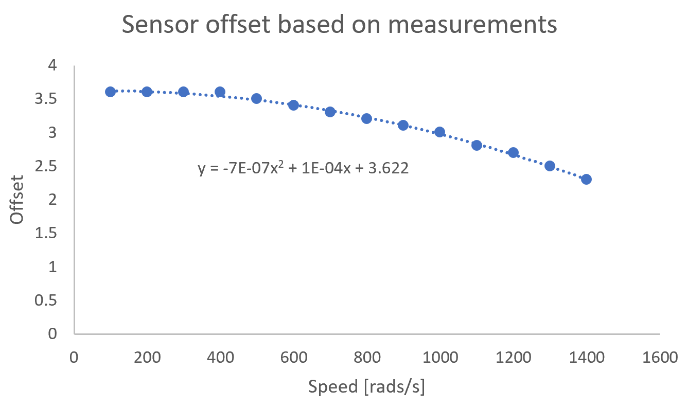
I tweaked the sensor offset manually at every speed so at to get the lowest multimeter-based current draw and then fitted the data as follow:
Since the new sensor value calculation was slowing down the main loop by 1 kHz, I chose to only update the value every 10 loops.
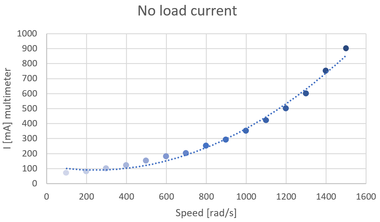
Pasting here the current measurements with this correction. Note that beforehand, with a static zero_electric_angle, at above 1000 rad/s I was maxing out my power supply at 5A.
All manual, tuning the offset value at every speed point. Since the current measure (which I was trying to minimize) was taken from a multimeter, I couldn’t really automate anything.
Same would be possible with the G4 implementation as it’s also using injected adc
[EDIT2] And you will see a difference even in voltage mode, because if current sense is initialized, those interrupts are triggered even if you are not in foc_current mode.
Just one doubt @runger , there are 2 ways to use current sense with G431.
The G431B-ESC specific one with DMA’s and no interrupt, and the generic G4 implementation that uses interrupts and injected adc?