# The inline current sensing
**URL:** https://community.simplefoc.com/t/the-inline-current-sensing/584
**Category:** hardware support
**Created:** [February 28, 2021, 1:28pm UTC](https://community.simplefoc.com/t/the-inline-current-sensing/584 "2021-02-28T13:28:36Z")
**Posts on this page:** 3
**Page:** 1
### Author:  [@kodaku](https://community.simplefoc.com/u/kodaku)
#### Post date: [February 28, 2021, 1:28pm UTC](https://community.simplefoc.com/t/the-inline-current-sensing/584/1 "2021-02-28T13:28:36Z")
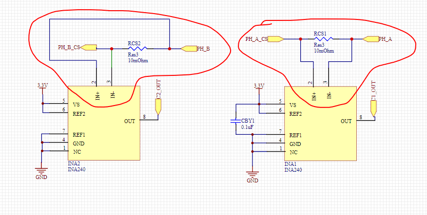
I want to ask, in the circuit of the simplefoc 2.0 version, the current sampling circuit, the one I drew in circles, seems to be reversed. Why is this?
---
### Author:  [@Antun\_Skuric](https://community.simplefoc.com/u/Antun_Skuric)
#### Post date: [February 28, 2021, 6:33pm UTC](https://community.simplefoc.com/t/the-inline-current-sensing/584/2 "2021-02-28T18:33:24Z")
It’s the convenience issue 😃
The best would be not to invert the shunt. This way you need to invert the gain in software.
It is the choicse that I’ve made in order to easier fit the current sensing on the board and to reduce the traces from shunts to the amplifier.
I would definitely suggest you to try avoiding the inversion if possible.
---
### Author:  [@kodaku](https://community.simplefoc.com/u/kodaku)
#### Post date: [March 1, 2021, 5:19am UTC](https://community.simplefoc.com/t/the-inline-current-sensing/584/3 "2021-03-01T05:19:18Z")
Thank you for your answers and suggestions 😀