Teensy 4.1 6PWM

That’s a lot better, however, without the exact components name/model/manufacturer and datasheets I cannot comment. Please also attach the BOM.

edit: I see you attached the BOM while I was typing let me have a look.

Google is asking me for login, any way to share this public?

If it is private please direct message me I will send you my email.

For our competition, we have to go 10 miles in 40 minutes. So we need to average 15 mph.

How do you measure the energy expended? Battery charge indicator?

We’re currently working on a board that will give us power readings from a current sensor and voltage divider. We’re trying to sort of prototype our own Joulemeter, but a Joulemeter is what they use for the competition. We have a joulemeter, but haven’t had our car working for an extended period of time to really test it out.

Could you help me find where that video is? Seems like it would be a good idea to implement two motors to our front two wheels. They could be on the same axis and coming from the same driver like you said. This would eliminate a lot of losses coming from our bicycle chain as well.

These are the rules for our competition. The battery we currently have was bought before I came on the team and I’ve had trouble finding it on the internet. This is the most similar battery I could find and it’s what we included in our BOM.

The battery we used last year we purchased and the competition allowed this. As a team, we’ve never built a battery cell. Do you think this would be worth our time to achieve a better efficiency?

I realized that I could copy the spreadsheet to my personal account and then it would let me share it (The university emails have some weird restrictions). Let me make the BOM available here.

Also, we were considering making a prototype driver board out of perf board. I think it would be a good exercise for our team, and it would be a good way to continue prototyping while we wait for our driver board to ship. I’m just not sure if a perf board can handle the type of current that we’re going to pull.

Ok, so 48v and 12Ah approximately.

That does limit the motor average power consumption, depending on cells discharge capacity. The battery you linked to says 1000w, I suppose that is the maximum allowed discharge.

This does not harmonize with 3KW motor, just saying. Unless you parallel x3 of those.

Maybe you do not want to max out the battery discharge capacity for 40 minutes, that could in worst case lead to a battery fire. You may wish to monitor the battery temperature.

Designing your controller, when choosing current sense resistor, you should probably target 20amp (960watt @48v) to get best possible resolution. Depending on your switching frequency, 20 amp is still no small achievement when it comes to thermal management.

Looking at your setup, the cool design of your vehicle w. sponsors and stuff, not to mention the super cool driver, I would consider rewinding your engine to fit your needs, instead of buying a new motor. That would provide you with the optimal torque within your battery discharge capacity, depending on how you go about it. Maybe you can even optimize your current motor with higher winding count per stator tooth.

What is your gear-ratio? Target RPM?

I see the motor you linked to further up this thread is sold in two versions. 130Kv and 65Kv. Which one is yours?

Finding the perfect balance between Kv rating, winding turns per tooth, power rating and torque, I think is a great learning experience for your class and all you need is new wire, which you probably already have at your facility?

Ok, I see the TI current sensor in your design is a Hall effect type, so disregard the current resistor, you still have to decide on current rating for best possible resolution within your application specific parameters.

We have the 130 KV version and they attached hall sensors inside the motor for us.

You probably know this tool? It really is awesome!

https://www.bavaria-direct.co.za/scheme/calculator/

But again, it depends. You could also use your budget on a better battery with higher discharge capability and just crank up the revs. You could argue that your goal is to win with a few labs.

The winner of the competition will be the Team with the highest energy efficiency result in their vehicle class and energy category, within the valid attempts as defined for each competition.

Regarding your challenges to get the motor spinning. Was it solved? Did you measure the resistance on the wires. Maybe someone already did rewind the thing and you are feeding the algorithm a wrong variable?

To give you an update: Our team has decided that we don’t have the time & resources to proceed with tunnel testing to find the coefficient of drag for our vehicle, and therefore optimize our road-load equation. So we looked at public data for similar vehicles, ran some rough calculations, and estimated that our vehicle will consume ~1.5-2kW at a coasting speed of 15-20mph. For our vehicle, we don’t anticipate many large inclines or need for much acceleration, but we would like to be able to pull ~5-6kW if necessary.

So we’re looking to choose a BLDC motor that runs most efficiently at this wattage. Our budget is $1-1.7k. Any suggestions on motors or where to look?

Hello All,

Since our last post, we’ve learned a LOT about how to choose the specs for the motor we need. Turns out, to have a fighting chance at the competition, we’d need to consume around 100W continuously at 15mph, not 1.5-2kW.

I’ve compiled some MATLAB code to back-calculate the torque we’d need to maintain a 15mph velocity according to vehicle parameters such as gear ratio, coefficient of drag, rolling resistance, etc. Here’s the MATLAB code, and a horribly disproportionate force diagram to go along with it.

%2022-2023 UMSM Road Load 

%parameters
r1 = 0.0127;                        %radius small gear (m)                 %MESS WITH THIS VARIABLE
r2 = 0.12465;                       %radius big gear (m)                   %MESS WITH THIS VARIABLE
r3 = 0.2413;                        %radius of rear wheel (m)
m = 100;                            %mass of vehicle + driver (kg)         %REFINE PARAM IF TIME
%m_motor = ;                        %mass of the motor (if needed for g/W)
g = 9.8;                            %Acceleration d/t gravity m/s^2
rho = 1.23;                         %density of air (kg/m^3)
v = 6.7056;                         %15mph
C_d = 0.1;                          %coefficient of drag                   %REFINE PARAM IF TIME
C_r = 0.008;                        %rolling resistance coefficient        %REFINE PARAM IF TIME 
A = 1.1696;                         %cross sectional area (m^2)            %REFINE PARAM IF TIME
Eff_Chain = 0.95;                   %Efficiency percentage of chain system %REFINE PARAM IF TIME
%Eff_Motor = 0.85;                  %Depends highly on the motor, could possibly make this a function for certain motors?


%forces 
F_d = 0.5*rho*v^2*C_d*A;            %foce of drag(N)
F_n = m*g;                          %normal force(N)
F_rr = F_n * C_r;                   %force of rolling resistance(N)
F_gc = F_rr + F_d;                  %force of ground on car (N) (force we need to produce to go 15mph)

%torque calculations
t2 = F_gc * r3;                     %torque on the rear axle(N-m)
F_sb = (t2/r2) / Eff_Chain;         %force on the chain(N)
t1 = F_sb * r1;                     %torque motor must produce(N-m)

I’m pretty sure that this code properly computes the torque that the motor must produce to maintain 15mph. Do you see any issues? With the current numbers, our required torque is 0.2866 N-m. So, I began looking at motor specs to find motors which are most efficient at this torque, with a higher torque capacity to allow us to accelerate up to speed. While looking at motor specs, some datasheets didn’t include raw efficiency, rather a mass-to-power ratio for the motor as specific operating ranges. Do the following calculations look correct for determining efficiency % of the motor from the mass-to-power ratio? Do we need to take into account losses in the ESC during this calculation, so the 44% would be efficiency of motor + ESC? This data seems to be specific to a certain propellor used with the motor. Would this influence our calculations?

We’re also considering if calculating the required torque is the right way to go. We were thinking that it’s possibly to go right into calculating the power required to move our vehicle at 15mph. After doing some searching, we found this equation:

Power = (Total forces on car (N)) * (Velocity of car(m/s)) / (Total Transmission Efficiency)

Plugging in our numbers, we find that the power required to move the car would be ~78W. Should we base our search on this number and look for motors most efficient at 78W and then mess with the gearing from there? Thank you for your help!

1 Like

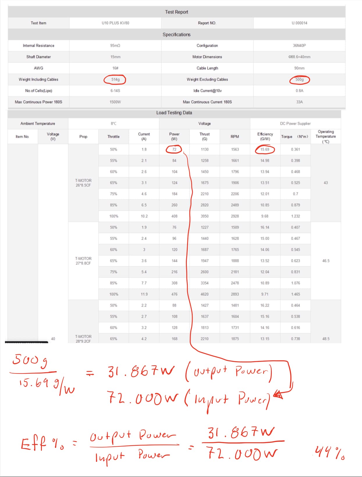
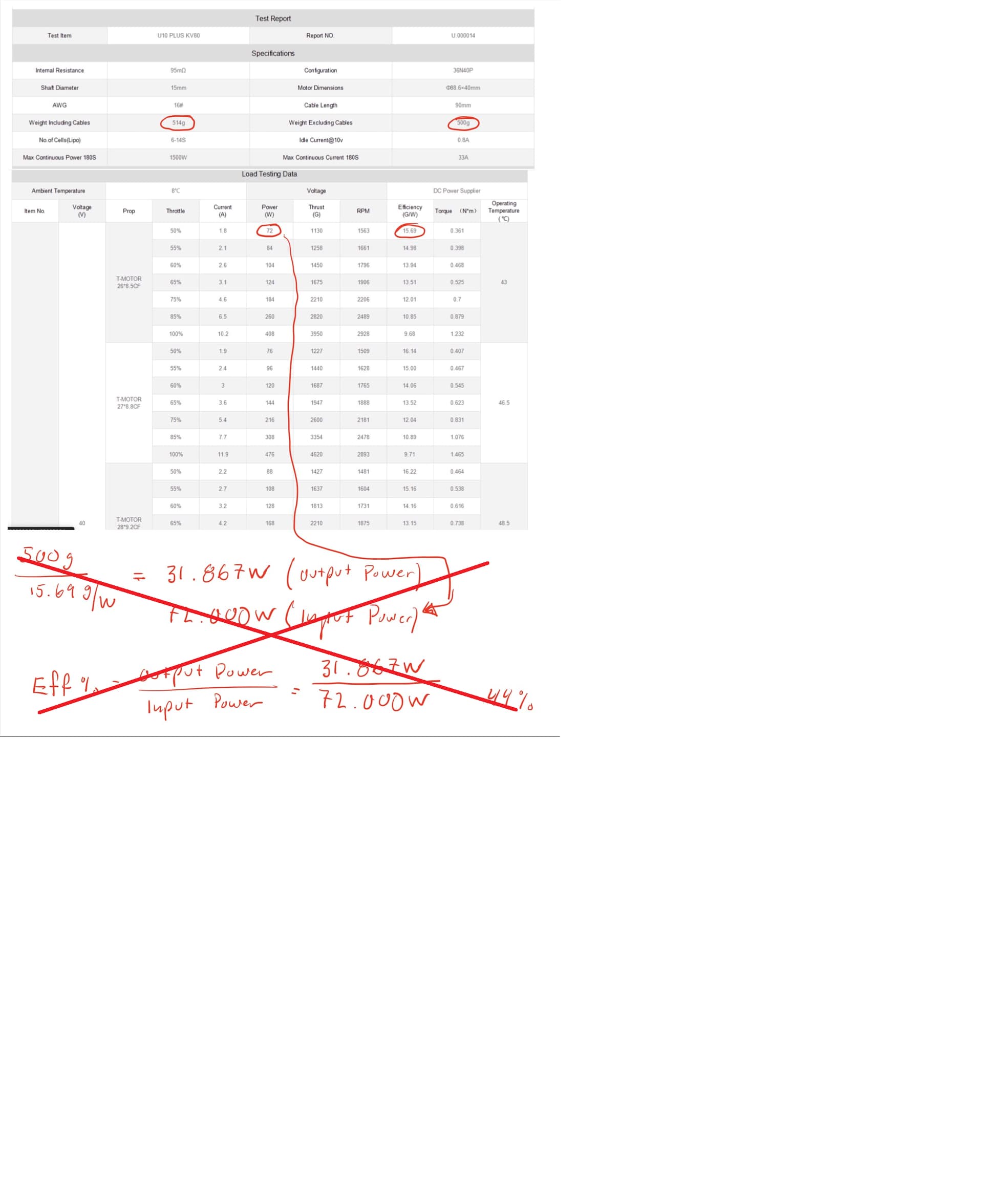
Fundamental assumption error: G/W is the thrust / watt ratio, not motor weight / watt ratio.

The thrust is the propeller vertical aerodynamic thrust, also dependent on the model and type of propeller, so the efficiency listed is irrelevant to your use case. I suggest you use 85% efficiency through-out as a constant.

Let me check the rest. I will post here.

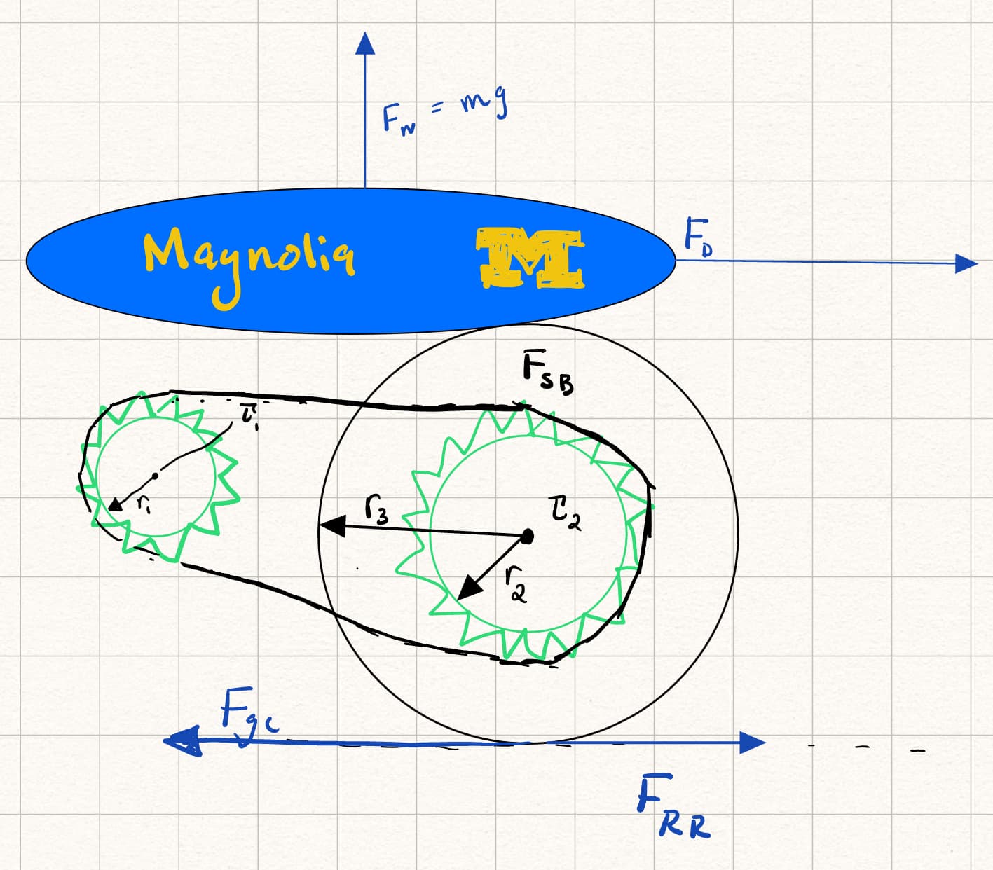
From your rear wheel and gear ratio I get:

265 RPM @ 15 mph

Gear ratio = 9.6

Motor RPM @ 15 mph = 2544

You need a motor that delivers maximum efficiency at 2544 rpm and most efficient at 78W. I calculated from your numbers load of about 72 Watts, using my method, so lets say the truth is around 75 watts.

The torque at 2544 rpm and 75 watts for that system would be 0.28 Nm, so your torque calculation is nearly spot-on, which is excellent.

You need a motor which could produce at least 3000 rpm, preferably 5000 RPM, because motors are usually most efficient in the mid-range of their RPM, and deliver at least about 0.3 Nm at max efficiency. Also it needs to go about 10 times more to accelerate, so max 5000 rpm and 3 Nm.

The motors you showed above are not in that range.

You need a bigger motor.

Most importantly, when calculating efficiency, the rolling resistance at low speeds and laminar flow is about 30/70 so the limiting factor in your system would be the rolling resistance, not transmission + driver efficiency or air drag. You MUST lower the rolling resistance. Also, your rolling resistance of 0.008 is probably a little too high, I would go for 0.005 (or even less, see table below) , which would decrease your wattage to about 50 W and increase the ratio of air drag / RR drag to about 40/60, if you use high quality LRR competition tires. You could get tires down to less than 10W resistance, even down to 7W, which would dramatically improve your efficiency. As you can see, the better tires are more important that a better motor.

Rolling Friction Coefficients
Some typical rolling coefficients:

Rolling Resistance Coefficient
c cl (mm)
0.001 - 0.002 0.5 railroad steel wheels on steel rails
0.001 bicycle tire on wooden track
0.002 - 0.005 low resistance tubeless tires
0.002 bicycle tire on concrete
0.004 bicycle tire on asphalt road
0.005 dirty tram rails
0.006 - 0.01 truck tire on asphalt
0.008 bicycle tire on rough paved road
0.01 - 0.015 ordinary car tires on concrete, new asphalt, cobbles small new
0.02 car tires on tar or asphalt
0.02 car tires on gravel - rolled new
0.03 car tires on cobbles - large worn
0.04 - 0.08 car tire on solid sand, gravel loose worn, soil medium hard
0.2 - 0.4 car tire on loose sand

Cheers,
Valentine

This is where the 2stage gearing comes into play. If you are serious about winning the competition, I think an acceleration/gearing and a cruising/gearing will be optimal. If so, you can then calculate the Kv needed w. your battery voltage in mente and then rewind your stator to suit your custom setup.

Too complicated I believe. The bad tires will shit on any efficiency gain they get from operating in the most efficient motor region. The rate limiting factor in the overall system is drag and rolling resistance.

My electric car efficiency dropped 10% just because I got new low efficiency tires. I went for high performance track tires, and paid for it. Good grip / fast tires are bad in the efficiency department. But efficient tires ride like rocks, so I figured my ass comfort is more important than my car efficiency.

I got a feeling they could win this if they just attach a $10 hoverboard motor from ebay in the back and get a REALLY good LRR tire to go with it as a direct drive, screw transmissions.

https://www.ebay.com/itm/265859060600?hash=item3de66f5378

The Indy track looks like that:

It’s diamond ground smooth surface, it rides like a dream. You could ride on a spring-loaded steel rim and get nearly 0 rolling resistance, forget about rubber. I’m even getting a little excited here.

1 Like

Ok, so they already have this awesome motor/rotor, which by the look of it, can be taken apart for a rewind. At the moment the motor w. a 48v battery is rated for 130Kv x 48v = 6.240 RPMísh. The only problem with it, as for as im told, is that it consumes too much power. Right, so in order to get more torque out of that motor at the needed 2500ish RPM, or lower even w. two-stage-gearing, you got to rewind. Its a simple matter of how strong you are in the electromagnetic force. And that motor they have, is strong in the force. At the moment the motor has 18mOhm internal resistance. Why not make that 0.18ohm?

If its for the larger magnets and you buy a custom wound motor, with a large enough budget, then I get that, but that would be for the magnets themselves, and I would then make sure they are of highest quality/specs.

@Skylar_Lennon Consider the two-stage gearing approach. The most torque is needed at take-off, so lets say your take-off gear is geared to get you the needed torque with a 1450 rpm/wound motor. The cruising, which has a completely different torque need, also needs to be geared for that same motor, but because the cruise gear no longer has to take off, it can have a lower gear ratio, and perhaps 1450rpm will cut it?

To go that low you will need Litz wire and up the frequency to 100kHz and more to get full advantage. But then you need to get really high end/quality MOSFETs. You may be asking way too much from college students for a club project.


image