@Antun_Skuric, how are you controlling your balance bot?
I’m using a PI + PID cascade if you were thinking of control structure. I’ll make sure to document this project well in next few weeks and explain the particular approach I’ve chosen in depth.
For remote control I’m using a HC-05 bluetooth miguel and an android app that I’ve made some time ago:
It was made for the project of a stepper based balancer few years ago:
Those all look great  Looking forward to finally finishing my rebuild and getting it to balance properly after I get back from holiday
I tried Giballo app today. I used readUserCommands() from Gibalo_Arduino. I don’t really like this way of control. In my opinion, better is standard joystick - Joy BT Commander app.
But Gibalo works also.
Hello @Marc_O,
There are two approaches really. Either you build a model and do a proper control theory controller calculations. Or you tune it in by hand. If you do have a model you can calculate the LQR controller or optimal PID controllers and similar.
Now if you do not have a model, there are two approaches that I’ve used:
- state space
- PID stabilisation + PID velocity cascade
Ti tune them i find it really useful to establish a very simple communication protocol as motor commands. You can see that in the Arduino code I’ve got a tuneConteoller() function that helps me tune in the values quicker.
So now how to tune stuff.
State space controller will have structure:
Voltage = k1*angle +k2*angular_velocity +k3*motor_velocity +k4*motor_position;
k1 and k2 are necessary for stabilisation. And you can put the other two to zero during the time you’re tuning those two. With the k3,k4=0 you have the same behavior as PD controller.
Once you’ve done with tuning you’ll have the balancing robot which stays upright but cannot really hold its postion and will tend run away from you. But it will stay upright.
They you start small on k3 and try find if the robot will stop. If you have a small error in you IMU angle 0, if its center of mass is not aligned 100% with the IMU zero value, you might still not be able to stop the robot to have a certain velocity when he stabilises. With the higher k3 you will add more important to the motor velocity so you’ll see the effect visually. Finally you can start small with the k4 and with this one you should be able to stabilises the balancing robot position. So your robot should more or less always return to the same point. But for me the key is really a fast iterating the values and seeing what do they do.
For PID stab + PID vel cascade. The procedure is the same.you first put all the values to 0 and tune good values for the PID stabilisation. First P and D and I optionally a bit at the end. Once when it is stable but not staying in one spot, tune the PID velocity. Start small and build up to what you need. PID velocity is a bit tricky to tu e because the importance of velocity should 'ot be to big ans large values can make the robot unstable very quickly. 
2 Likes
WOW! …ok, next, an MIT Cheetah.
Hey guys,
It has passed some time from the last balancing robot video ![]()
Therefore here is one short robustness testing video to break the silence!

Someone working on some new desing?
7 Likes
Hi
I saw your video on youtube very impressive. Tell me if the control uses the model of the robot and its size. I am going to build a similar robot but with more powerful motors. Do I need to change anything in the control. If I want to add legs to the robot like in the boston dynamics handle will it be difficult?
Hi @German_io,
For the control look at this post of Antun.
If you are going to build a different balancing robot with different weight distribution and motors, then you need to change the PID values for both PID controllers. Lots of guides can be found online on how to tune these values.
If you are going to add legs and you want that these legs will dynamically move with the robot just as handle, then the job will be harder! If you have not build a balancing robot before, I would suggest first to try building one without legs. Once you have mastered that, then you can always add legs later! Good luck with your project! 
@German_io
Antun posted his code here:
I stole bits of it for a much large balancing bot and it was very useful. I had to split his control code across two MCUs (comms via can bus) due to my separate motor drivers (Dual VESC).
So, now I try to built my self balancing robot. This is my setup.
2 as5047 sensor. 2 5008 motors (7pp, 0.128 omhs)
Drv8302 like drivers. No current sensing.
Now I need to advice.
How can I tune parameter and pid values for stabilisation ?
Maximal voltage like torque value for my motor 3 volts
I try to code Antur but motors moving all time.
I test motors move in similar direction.
I test IMU (it works some slowly but it works normal ( the values some falling behind from mechanical moving but in Antur video it works also)
I need all your advices 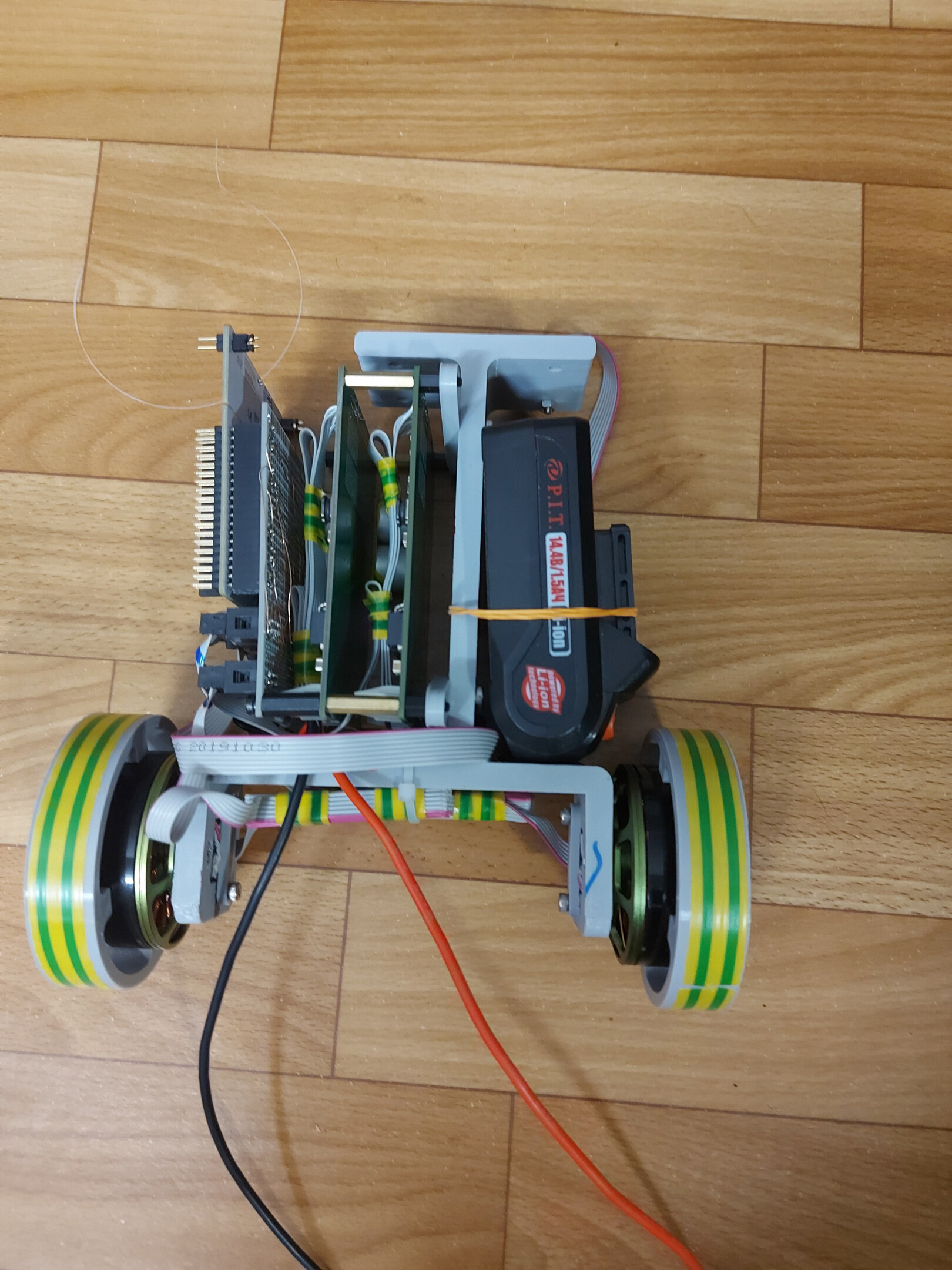
#include <SimpleFOC.h>
#include “imu_helpers.h”
#define INH_A_1 PC6
#define INH_B_1 PC9
#define INH_C_1 PC8
#define EN_GATE_1 PB10
#define M_PWM_1 PA11
#define M_OC_1 PB12
#define OC_ADJ_1 PC4
#define INH_A_2 PA8
#define INH_B_2 PA9
#define INH_C_2 PA10
#define EN_GATE_2 PB3
#define M_PWM_2 PB5
#define M_OC_2 PB4
#define OC_ADJ_2 PA12
BLDCMotor motor1 = BLDCMotor(7);
BLDCMotor motor2 = BLDCMotor(7);
BLDCDriver3PWM driver1 = BLDCDriver3PWM(INH_A_1, INH_B_1, INH_C_1, EN_GATE_1);
BLDCDriver3PWM driver2 = BLDCDriver3PWM(INH_A_2, INH_B_2, INH_C_2, EN_GATE_2);
MagneticSensorSPI sensor1 = MagneticSensorSPI(AS5147_SPI, 10);
MagneticSensorSPI sensor2 = MagneticSensorSPI(AS5147_SPI, 9);
PIDController pid_stb{.P = 3, .I = 5, .D = 1, .ramp = 1000, .limit = 3};
PIDController pid_vel{.P = 0.01, .I = 0.03, .D = 0, .ramp = 10000, .limit = _PI / 10};
LowPassFilter lpf_pitch_cmd{.Tf = 0.07};
LowPassFilter lpf_throttle{.Tf = 0.5};
LowPassFilter lpf_steering{.Tf = 0.1};
float steering = 0;
float throttle = 0;
float max_throttle = 10; // 20 rad/s
float max_steering = 1; // 1 V
int state = 1; // 1 on / 0 off
Commander commander = Commander(Serial);
void cntStab(char* cmd) { commander.pid(&pid_stb, cmd);}
void cntMove(char* cmd) { commander.pid(&pid_vel, cmd);}
void lpfPitch(char* cmd) { commander.lpf(&lpf_pitch_cmd, cmd);}
void lpfSteering(char* cmd) { commander.lpf(&lpf_steering, cmd);}
void lpfThrottle(char* cmd) { commander.lpf(&lpf_throttle, cmd);}
void setup() {
// M_OC - enable overcurrent protection
pinMode(M_OC_1,OUTPUT);
digitalWrite(M_OC_1,LOW);
// M_PWM - enable 3pwm mode
pinMode(M_PWM_1,OUTPUT);
digitalWrite(M_PWM_1,HIGH);
// OD_ADJ - set the maximum overcurrent limit possible
// Better option would be to use voltage divisor to set exact value
pinMode(OC_ADJ_1,OUTPUT);
digitalWrite(OC_ADJ_1,HIGH);
pinMode(M_OC_2,OUTPUT);
digitalWrite(M_OC_2,LOW);
// M_PWM - enable 3pwm mode
pinMode(M_PWM_2,OUTPUT);
digitalWrite(M_PWM_2,HIGH);
// OD_ADJ - set the maximum overcurrent limit possible
// Better option would be to use voltage divisor to set exact value
pinMode(OC_ADJ_2,OUTPUT);
digitalWrite(OC_ADJ_2,HIGH);
Serial.begin(250000);
// initialise encoder hardware
sensor1.init();
sensor2.init();
// link the motor to the sensor
motor1.linkSensor(&sensor1);
motor2.linkSensor(&sensor2);
// power supply voltage [V]
driver1.voltage_power_supply = 14;
driver1.init();
motor1.linkDriver(&driver1);
motor1.voltage_limit=3;
motor1.voltage_sensor_align = 0.5;
driver2.voltage_power_supply = 14;
driver2.init();
motor2.linkDriver(&driver2);
motor2.voltage_limit=3;
motor2.voltage_sensor_align = 0.5;
// set control loop type to be used
// using voltage torque mode
motor1.controller = MotionControlType::torque;
motor2.controller = MotionControlType::torque;
// enable monitoring
motor1.useMonitoring(Serial);
motor2.useMonitoring(Serial);
// initialise motor
motor1.init();
motor2.init();
motor1.initFOC();
motor2.initFOC();
_delay(1000);
if ( !initIMU() ) {
Serial.println(F(“IMU connection problem… Disabling!”));
return;
}
_delay(1000);
// add the configuration commands
commander.add(‘A’, cntStab, “pid stab”);
commander.add(‘B’, cntMove, “pid vel”);
commander.add(‘C’, lpfThrottle, “lpf vel command”);
commander.add(‘D’, lpfPitch, “lpf throttle”);
commander.add(‘E’, lpfSteering, “lpf steering”);
Serial.println(F(“Balancing robot ready!”));
}
void loop() {
// iterative setting FOC phase voltage
motor1.loopFOC();
motor2.loopFOC();
// iterative function setting the outter loop target
motor1.move();
motor2.move();
if (!state) { // if balancer disabled
motor1.target = 0;
motor2.target = 0;
} else if ( hasDataIMU() ) { // when IMU has received the package
// read pitch from the IMU
float pitch = getPitchIMU();
// calculate the target angle for throttle control
float target_pitch = lpf_pitch_cmd(pid_vel((motor1.shaft_velocity+motor2.shaft_velocity) / 2 - lpf_throttle(throttle)));
// calculate the target voltage
float
voltage_control = pid_stb(target_pitch - pitch);
// filter steering
float steering_adj = lpf_steering(steering);
// set the tergat voltage value
motor1.target = voltage_control + steering_adj;
motor2.target = voltage_control - steering_adj;
}
// read the tuning commands from Serial
commander.run();
// read the user command from bluetooth
}
/**
Function intended for connecting to the Gibalo application
In one byte it receives either throttel or steering command
- if received byte in range [0,200] then throttle command in between [-100, 100]
- if received byte in range [210,250] then steering command in between [-20, 20]
*/
Hi @German_io,
Your balancing robot looks awesome! Great job  .
.
Antun wrote a small piece on how to balance the robot.
Assuming that the IMU and the motors are all working correctly, I can also give my advice/experience on tuning a balancing robot:
- Set PID for stabilisation and velocity both to zero.
- First start with the PID for stabilisation (the hard one)
2.1 First make the P value higher and higher until you notice that it starts to balance a bit (it will still fall now). Don’t go to high because it will start shaking!
2.2 Increase the I value to let it better react to larger disturbances. Don’t go to high because it will start shaking!
2.3 Increase D value (small steps) to smooth it out, don’t go to high here because that will make the system unstable. - If your robot can balance by itself, then it is time to work on the velocity PID (to let it stand still).
3.1 Again use small steps here but this one will be easier.
Sometimes you have to go back some steps to make it work more properly, or try something completely different.
To make this all easier, you could connect some potentiometers to tune these values in real-time!
Good luck
Thanks for your advices. What about lpf values and ramp values? Do I need to tuning it?
How can I tune lpf values?
For the velocity LPF, you can use it to smooth your velocity. Start at a very small value (maybe 0, or 0.0025 and increase it until you are satisfied with the “smoothness”). A value of 0.05 would be quite a high value, in my experience, and I would not go beyond that.
You can also set the motor.motion_downsample, for example to a value like 4. This determines how often the move() function is run compared to the loopFOC(), and especially on fast MCUs this can be a good thing to do.
I have some problems with mpu6050. When I use Serial.println(getPitchIMU) and I rotate the module the data from sensor changing very slow. What is it ?
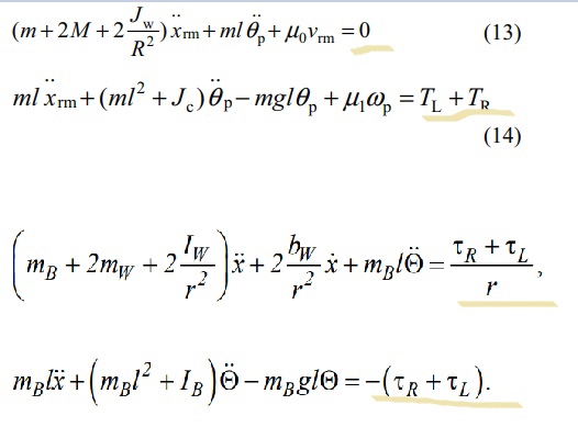
Can anyone give me advise. Now im trying to do mathematical model for my balancing robot. And i not understand some moments.
I have 2 different science article and 2 similar (but different equation)
Why it is?
The main systems is the same but the result is different?