# PWM pins are incorrectly mapped
**URL:** https://community.simplefoc.com/t/pwm-pins-are-incorrectly-mapped/6624
**Category:** developement
**Tags:** stm32
**Created:** [January 23, 2025, 1:48am UTC](https://community.simplefoc.com/t/pwm-pins-are-incorrectly-mapped/6624 "2025-01-23T01:48:54Z")
**Posts on this page:** 2
**Page:** 1
### Author:  [@osugiw](https://community.simplefoc.com/u/osugiw)
#### Post date: [January 23, 2025, 1:48am UTC](https://community.simplefoc.com/t/pwm-pins-are-incorrectly-mapped/6624/1 "2025-01-23T01:48:54Z")
I’m using Nucleo-STM32G431RB and the board controller from the Infineon PMSM\_LV\_15W\_Card. All the physical wiring and pin assignment are correctly matched with 6 PWM pins capabilities, but the Software initialization tell me that some pins don’t support Timer for PWM (Pin 26 = PB10). While based on ST Datasheet that pin support for PWM.
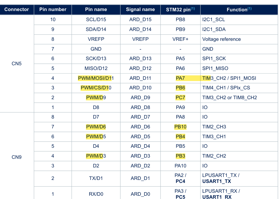
Serial Monitor Output:

This is my platform.ini:
> [env:nucleo\_g431rb]
> platform = ststm32
> board = nucleo\_g431rb
> framework = arduino
> debug\_tool = stlink
> monitor\_speed = 115200
> upload\_protocol = stlink
> lib\_deps = askuric/Simple FOC@^2.3.4
> lib\_archive = false
My Code:
> #include \
> #include \
>
> /\* Hall Sensor Pins \*/
> #define PIN\_HALL\_A PA\_0
> #define PIN\_HALL\_B PA\_1
> #define PIN\_HALL\_C PA\_4
>
> /\* BLDC Driver Pins \*/
> #define PIN\_PWM\_LIN1 PB\_3
> #define PIN\_PWM\_LIN2 PB\_4
> #define PIN\_PWM\_LIN3 PB\_10
>
> #define PIN\_PWM\_HIN1 PC\_7
> #define PIN\_PWM\_HIN2 PB\_6
> #define PIN\_PWM\_HIN3 PA\_7
>
> /\* Current Sense Pins \*/
> #define PIN\_ADC\_IU PB\_0
> #define PIN\_ADC\_IV PC\_1
> #define PIN\_ADC\_IW PC\_0
>
> /\* Motor Characteristics\*/
> #define POLE\_PAIRS 4
> #define PHASE\_RESISTANCE 6.85 // (13.7 / 2)
> #define PHASE\_INDUCTANCE 3.865 // (7.73 / 2)
> #define KV\_RATING 195
>
> /\* Current Sense \*/
> #define SHUNT\_RESISTOR 0.05
> #define GAIN\_AMPLIFIER 16.4
>
> // BLDCMotor( pole\_pairs , ( phase\_resistance, KV\_rating optional) )
> BLDCMotor motor = BLDCMotor(POLE\_PAIRS, PHASE\_RESISTANCE, KV\_RATING, PHASE\_INDUCTANCE);
>
> // BLDCDriver6PWM( pin\_pwmAH, pin\_pwmAL, pin\_pwmBH, pin\_pwmBL, pin\_pwmCH, pin\_pwmCL, enable (optional))
> BLDCDriver6PWM driver = BLDCDriver6PWM(PIN\_PWM\_HIN1, PIN\_PWM\_LIN1, PIN\_PWM\_HIN2, PIN\_PWM\_LIN2, PIN\_PWM\_HIN3, PIN\_PWM\_LIN3);
>
> // HallSensor(int hallA, int hallB , int hallC , int pole pairs)
> HallSensor sensor = HallSensor(PIN\_HALL\_A, PIN\_HALL\_B, PIN\_HALL\_C, POLE\_PAIRS);
>
> // LowsideCurrentSense(shunt\_resistance, gain, adc\_a, adc\_b, adc\_c)
> LowsideCurrentSense current\_sense = LowsideCurrentSense(SHUNT\_RESISTOR, GAIN\_AMPLIFIER, PIN\_ADC\_IU, PIN\_ADC\_IV, PIN\_ADC\_IW);
>
> // Interrupt routine initialization
> // channel A and B callbacks
> void doA(){sensor.handleA();}
> void doB(){sensor.handleB();}
> void doC(){sensor.handleC();}
>
> void setup() {
> Serial.begin(115200); // use monitoring with the BLDCMotor
> SimpleFOCDebug::enable(&Serial);
>
> /\* Initialize Hall Sensor \*/
> sensor.init(); // initialize encoder hardware
> sensor.enableInterrupts(doA, doB, doC); // hardware interrupt enable
> motor.linkSensor(&sensor); // link the motor to the sensor
>
> /\* Initialize BLDC Driver \*/
> driver.pwm\_frequency = 20000; // pwm frequency to be used [Hz]
> driver.voltage\_power\_supply = 18; // power supply voltage [V]
> driver.voltage\_limit = 18; // Max DC voltage allowed - default voltage\_power\_supply
> int driverStatus = driver.init(); // driver init
> Serial.printf(“Driver init status %d\n”, driverStatus);
> motor.linkDriver(&driver); // link the motor to the driver
>
> // current\_sense.linkDriver(&driver); // link the driver with the current sense
> // motor.linkCurrentSense(¤t\_sense); // link the motor to current sense
> // motor.useMonitoring(Serial); // monitoring port
>
> // motor.controller = MotionControlType::velocity; // set control loop type to be used
> // motor.init(); // initialize motor
> // current\_sense.init(); // init current sense
>
> // // align encoder and start FOC
> // motor.initFOC();
> }
>
> void loop() {
> // // FOC algorithm function
> // motor.loopFOC();
>
> // // velocity control loop function
> // // setting the target velocity to 2rad/s
> // motor.move(2);
>
> // // monitoring function outputting motor variables to the serial terminal
> // motor.monitor();
> }
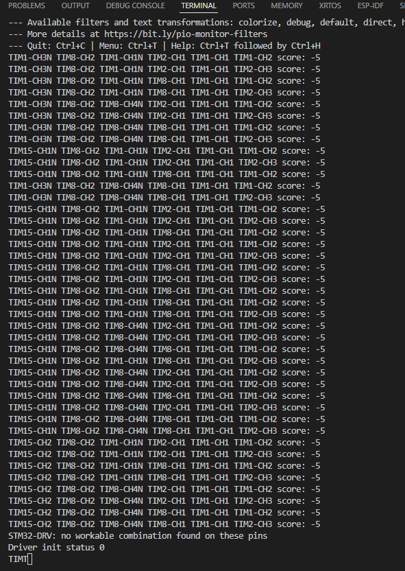
After changing the PB10 to other pin it appears as follow:
Thank you in advance!
---
### Author:  [@Antun\_Skuric](https://community.simplefoc.com/u/Antun_Skuric)
#### Post date: [January 24, 2025, 4:38pm UTC](https://community.simplefoc.com/t/pwm-pins-are-incorrectly-mapped/6624/2 "2025-01-24T16:38:14Z")
6PWM is very tricky and sensitive. Ensuring that all pins are capable of generating PWM is not enough.
You should make sure either to use the same timer for all 6 pins (typically timers 1 or 8) or have one timer per phase (per high/low pwm pair).
I believe that your pins do not blong to any of the two categories. Am I missing something?
Here is a link to our pin mapping docs for your stm32 variant: [G431R(6-8-B)(I-T)\_G441RB(I-T) Pinout | STM32 Pinouts](https://docs.simplefoc.com/stm32pinouts/STM32G4xx/G431R(6-8-B)(I-T)_G441RB(I-T)/pinout)
Here is the docs section that talks about choosing PWM pins for stm32.
> **[Choosing PWM pins](https://docs.simplefoc.com/choosing_pwm_pins#stm32-boards)**
>
> Arduino Simple Field Oriented Control (FOC) library .