Where exactly is that code for the lepton yo ucommitted? I want to comb through it and compare my code to see if it sheds light on where mine is going wrong.
Here: GitHub - simplefoc/simplefoc_lepton_platformio: Firmware for the SimpleFOC Lepton Board by Valentine
The code is in the src/main.cpp file.
Yes, exactly… the different voltage levels you can set are the “vertical axis” of your sine-wave, and the “horizontal axis” is time, so determined by your loop iteration speed. Together you can see these things form a “grid” on which the controller can place the “samples” I was talking about earlier. So the whole thing is a discretization of the sine wave. The more samples you can place, the more accuracy you have in terms of voltage levels, the more faithfully you can re-produce the sine wave.
I would assume this is possible, you could design the control loop to use a “position estimator” instead of the sensor. The estimator would read the sensor at some frequency, but provide values to the control loop at a higher frequency, using some kind of interpolation logic in-between.
But this will be a challenging implementation, and a hard pre-requisite to being able to do it will be to have a 100% working setup to start from. It’s impossible to do it without being able to verify what’s going on empirically.
Yeah, and it will take memory, too. That’s why I’m in a rush to upgrade to a better MCU. There are bound to be things I need to do, and even the most elementary program has to be absolutely squeezed into the lepton.
To be fair I am now having a similar problem with the blue pill. The flash is too small to run the commander. Once again it highlights the need for at least one flagship combo of hardware and code base that is reasonably flexible.
What we have right now is a bunch of parts lying around. Every single time I try any combination there are so, so many problems and barriers it’s ridiculous. It’s not a building block that can be stood upon.
I managed to get the open loop working with the bluepill, and the angle sensor. When I try the code I posted most previously, minimally adapted to make it fit the blue pil, it exhibits the same behavior, so now I at least know it’s not the lepton. I will follow Deku’s advice, but I think there is something the Commander does when it executes a command which I am not doing in my code, or something I am messing up.
Somehow, torque control mode is not being engaged, I think. It’s doing angle mode with some random angle, or something. I tried reloading the library in case, no dice.
That doesn’t explain the second weak spot, though. As I rotate the rotor, it has two weak spots. One stable point where the rotor started, and one about halfway around, which is not quite stable but pretty close. Like the space vector voltage curve… hm pretty sure that’s not related unless some wires got crossed in a remarkable coincidence of some kind.
Additionally, may we reflect for a moment perhaps, I’ve spend maybe 5 working days on this, = 200 bucks a day at least, so 1000 bucks, plus 240 for the boards and shipping, the frustration, and we aren’t done yet. At least $1240, at $3 per board, that’s a lot of boards to sell before you save that money. It wouldn’t solve all the problems here, but I’m just trying to point out that a couple extra bucks per board is a good deal if it makes things work better, even just in the development stage, even if you are making a lot of products that include said boards.
When I read the datasheets of other motor driver chips and boards, a lot of them hawk their “code free” stuff, precisely because it saves dev time. It’s a legit thing to save dev time, and people will accept higher per unit cost for sure. Esp when the per unit cost isn’t really the engineer’s problem.
The commander just executes whatever command you attached to it. For example:
void doTarget(char* cmd) { command.scalar(&motor.target, cmd); }
void doLimitCurrent(char* cmd) { command.scalar(&motor.current_limit, cmd); }
the setup in the beginning defines what command is attached to the commander function. What function are you running via commander that is not working in the configuration when you hardcode it?
I don’t think that anyone will argue that development is cheap. There is a saying: good, cheap, fast - pick two. I think if you want something developed quickly, and you want it to be good, you might be more interested in buying something like ODrive, which of course is at cost (and inspired this project to some point).
The holy uncertainty principle trinity of all engineering projects:
- Features
- Cost
- Time to market
1 Like
As mentioned in the Lepton Deku Mod thread, I will be doing exactly this today. I was debating how to implement it just for digital hall sensors, but if it can be useful for other sensors like this I will make it generic. It was looking like it would have to hook in at the motor level anyway, since the estimation needs to be done using the filtered velocity.
I wonder if you could implement a hardware RC filter to the ADC input in a way that for a certain range of speeds (filter frequency response), a single hall sensor will produce a smoothed analog voltage related to speed. Maybe the pull-up/down for the hall sensor also needs to be adjusted in that case.
What approach were you thinking?
estimatedAngle = sensorAngle + velocity * (currentTime - timeWhenSensorWasRead)
I think velocity will be the filtered value returned by FOCMotor::shaftVelocity(), sensorAngle will be the last unfiltered reading of the sensor, and then estimatedAngle will be fed into the angle low-pass in FOCMotor::shaftAngle(). But it’s possible the velocity will need to be a snapshot from the time the sensor was read, and sensorAngle will need to be a snapshot of the filtered shaft angle.
Hopefully tuning the filter time constants will be all that’s necessary to get it stable. I may also need to add a second order prediction, using velocity history to calculate acceleration, and multiply that by delta time squared.
It would be nice to have a test rig with both digital halls and a magnetic encoder to see how closely the estimate tracks the true position, and how it deviates during speed changes. Or on second thought, a magnetic encoder alone should do it. Read it at high frequency, but have a variable to control how often the prediction algorithm’s sensor value is updated. That way I can test the accuracy of the prediction over a wide range of sample rates.
EDIT: What the heck! First try it works perfectly ![]() Simple as adding this to BLDCMotor::move, just after the angle/velocity update:
Simple as adding this to BLDCMotor::move, just after the angle/velocity update:
shaft_angle += shaft_velocity * (_micros() - sensor->angle_prev_ts);
So that is using the filtered angle and velocity to perform the prediction.
I edited the HallSensor class to use angle_prev_ts instead of its pulse_diff variable, and override Sensor::update() to do nothing (the only useful thing it did was the full rotations check, which is now in HallSensor::updateState).
Sensor::angle_prev_ts is protected, so we’ll either need to make it public or add a get function for BLDCMotor to use it like that.
@dekutree64 this is kind of awesome!
Do you think it could be implemented as a Sensor class, like:
BLDCMotor motor = ...
SomeSensor wrappedSensor = ...
SmoothingSensor sensor = SmoothingSensor(&wrappedSensor, &motor);

void setup() {
...
wrappedSensor.init();
sensor.init();
motor.linkSensor(sensor);
...
}
The reason being that this way of doing it could work with any other sensor, and would not need modifications to the BLDCMotor class?
Only if the low-pass filtering is moved into the sensor class instead of the BLDCMotor shaftAngle and shaftVelocity functions. But that would involve modifying both BLDCMotor and FOCMotor…
I think it’s better to make it an option in BLDCMotor, as it really is only that one line then. Just a boolean to enable angle prediction, and perhaps a downsampling for the sensor->update() call in BLDCMotor::loopFOC so Anthony’s slow I2C sensor can be called less often.
I need to try tuning the velocity and angle PIDs for this motor and make sure it doesn’t cause any weird effects. Torque-voltage mode spins smoothly and equal speed in both directions, and responds well to my changing the speed by turning a servo tester knob. But high frequency torque/speed changes from PID may be another story.
But by providing the motor object to the SmoothingSensor class, you could access motor->shaft_velocity directly from the sensor? Or is that not enough?
If I’m not mistaken, that will cause an infinite recursion as sensor->getAngle() would call motor->shaftAngle() to get the filtered value for the prediction, and that calls sensor->getAngle().
I think motor will call sensor.update() on the SmoothingSensor, which will just read motor->shaft_velocity (not the function call but the field which contains the previously calculated, smoothed velocity) and call wrappedSensor.update() and wrappedSensor->getAngle() to get the new raw angle…
I like this better because it separates the position estimation code from the motor code, and works with any sensor.
And it also means that it can be potentially composed with other wrapping sensors like the CalibratedSensor and others that we might come up with in the future…
Ok, here’s what I’ve got:
class SmoothingSensor : public Sensor
{
public:
  SmoothingSensor(Sensor *s, const FOCMotor *m):wrappedSensor(s),motor(m){}

  float getMechanicalAngle() { return wrappedSensor->getMechanicalAngle(); }
  double getPreciseAngle() { return wrappedSensor->getPreciseAngle(); }
  float getVelocity() { return wrappedSensor->getVelocity(); }
  int32_t getFullRotations() { return wrappedSensor->getFullRotations(); }
  int needsSearch() { return wrappedSensor->needsSearch(); }

  void update() {
    if(sensor_cnt++ < sensor_downsample) return;
    sensor_cnt = 0;
    wrappedSensor->update();
  }

  float getAngle() {
    return enable_smoothing == false ? wrappedSensor->getAngle() :
      wrappedSensor->getAngle() + (motor->shaft_velocity * _micros() - wrappedSensor->angle_prev_ts);
  }

  bool enable_smoothing = true;
  unsigned int sensor_downsample = 0; // parameter defining the ratio of downsampling for sensor update
  unsigned int sensor_cnt = 0; // counting variable for downsampling

protected:
  float getSensorAngle() { return wrappedSensor->getSensorAngle(); }
  void init() { wrappedSensor->init(); }

  Sensor *wrappedSensor;
  const FOCMotor *motor;
};
This class has to be declared a friend of Sensor so it can access wrappedSensor->angle_prev_ts and the protected functions.
It’s a bit different this way since it’s using the unfiltered getAngle for prediction and then filtering the result, but that may be more correct anyway, I’m not sure. Sensor::minDeltaT can’t be properly passed through to the wrapped sensor this way, but I suppose that’s not typically changed from the default anyway…
I need to set up a motor with a magnetic encoder to properly test it. My initial success may or may not have been due to the prediction algorithm. When I first changed from doing the prediction in BLDCMotor::move to this class, I accidentally left motor.linkSensor using the HallSensor directly rather than going through the SmoothingSensor, and yet it ran just fine. Previously this motor only ran well in one direction, so I am confused. Now it works with or without smoothing, and really I can’t tell much difference either way.
Tuning the voltage-based current limiting wasn’t much trouble. I ended up on 1400kv, which is a fair bit higher than the 990 that this motor should be, but I think is within typical range.
PID tuning is as fiddly as ever, and I never did get it quite right. I’ll try again tomorrow.
2 Likes
Never got time to work on it yesterday, but did manage to get a few minutes in earlier today.
It occurred to me the difference from before when it ran poorly in one direction is that now I’m using SinePWM instead of Trapezoid120, so maybe the low-pass filtering is already smoothing the shaft angle and allowing setPhaseVoltage to provide a smoother signal than trapezoid.
Velocity PID is now tuned, with values 0.01, 0.1, 0. Runs very smoothly and velocity tracks well.
I still can’t tell any difference at all whether SmoothingSensor.enable_smoothing is enabled or not. I thought maybe wrappedSensor.angle_prev_ts was getting updated just before every prediction so the delta time was always basically zero, but my modified HallSensor class only updates it when a sensor changes state, so that’s not it. Although with other sensors that would be the case when sensor_downsample is zero, since motor.loopFOC always calls sensor.update shortly before motor.move calls sensor.getAngle.
Does it maybe become more noticeable in some situations, like when turning very slowly?
Update on the Lepton testing: I’ve hooked up a motor, and tested different SPI sensors.
I could not make it work well with the SC60228 so far, although I did get the sensor working with the dev branch code (which has some bug-fixes compared to the release version) and by changing SPI Mode. Not sure what the problem is, TBH.
I then tested it with the MA330, and it seems to be working quite well. Tuning the PID without commander is a pain though. With the settings I have right now on an eMax GB4008 (66KV) turns well enough, draws hardly any power in velocity mode, and get it up to 75rad/s at 15V, that’s with about 3.5kHz loop speed…
More tomorrow.
2 Likes
Do you think Deku’s interpolator might help with loop speed? Sorry I haven’t gotten anything done recently… tomorrow I can experiment further to try to solve the baffling problem with the shaking stuff. My first stop will be a different sensor and magnet positioning approach, I bought an AS5048B. Or maybe I will try adjusting the distance of the magnet from the sensor… Or experiment to see if I can ascertain the cause of the variation between the pole pair check in the commander sketch and the pole pair check sketch… Probably switching out the sensor and magnet and magnet holder is the fastest way to get answers.
Well no wonder it didn’t do anything, that code was total nonsense ![]() Hopefully this one is not so bad:
Hopefully this one is not so bad:
class SmoothingSensor : public Sensor
{
public:
  SmoothingSensor(Sensor *s, const FOCMotor *m):wrappedSensor(s),motor(m){}

  float getVelocity() { return wrappedSensor->getVelocity(); }
  int needsSearch() { return wrappedSensor->needsSearch(); }

  float getMechanicalAngle() {
    return enable_smoothing == false ? wrappedSensor->getMechanicalAngle() : _normalizeAngle(
      wrappedSensor->getMechanicalAngle() + motor->shaft_velocity * (_micros() - wrappedSensor->angle_prev_ts) / 1000000.0);
  }

  float getAngle() {
    return enable_smoothing == false ? wrappedSensor->getAngle() :
      wrappedSensor->getAngle() + motor->shaft_velocity * (_micros() - wrappedSensor->angle_prev_ts) / 1000000.0;
  }

  double getPreciseAngle() {
    return enable_smoothing == false ? wrappedSensor->getPreciseAngle() :
      wrappedSensor->getPreciseAngle() + motor->shaft_velocity * (_micros() - wrappedSensor->angle_prev_ts) / 1000000.0;
  }

  int32_t getFullRotations() {
    float angle = getAngle();
    return (angle - _normalizeAngle(angle)) / _2PI;
  }

  void update() {
    if(sensor_cnt++ < sensor_downsample) return;
    sensor_cnt = 0;
    wrappedSensor->update();
  }

  bool enable_smoothing = true;
  unsigned int sensor_downsample = 0; // parameter defining the ratio of downsampling for sensor update
  unsigned int sensor_cnt = 0; // counting variable for downsampling

protected:
  float getSensorAngle() { return wrappedSensor->getSensorAngle(); }
  void init() { wrappedSensor->init(); }

  Sensor *wrappedSensor;
  const FOCMotor *motor;
};
First of all, I had the parentheses in the wrong place in the getAngle calculation.
Second, the delta time was in microseconds and needed to be divided by 1000000.
Third, loopFOC uses electricalAngle, which uses sensor->getMechanicalAngle and thus was getting the un-smoothed value.
Since getAngle is ultimately only used in angle mode and I was testing in velocity mode, it really wasn’t doing anything at all.
It does seem to work now. It’s able to achieve about 25% higher speed, 150rad/s versus 120rad/s without smoothing. 2208 motor rewound from 13T delta 1450kv to 11T wye so theoretically 990kv. Voltage limit is set to 1, so speed should be 990*2pi/60=103rad/s. 120 without smoothing implies 1147kv, 150 with smoothing implies 1433kv. When tuning voltage-based torque control without smoothing, I ended up on 1400kv giving the best behavior. I need to try measuring kv using the method of spinning it with a drill and measuring the AC voltage on the terminals and see how that compares.
It seems to need different PID tuning with smoothing turned on. This time with smoothing disabled I ended up on P0.1, I1.0, D0, and angle P20. That seems to give good behavior in velocity and angle mode. But with smoothing enabled, angle mode was a little choppy. P0.05, I0.1, D0, angle P5 seems to work well.
There is an audible difference between smoothing and not. Without smoothing, I can hear a sort of chirpy tone when the motor is spinning, one chirp for each hall state change. With smoothing, that goes away for the most part but I still hear it intermittently. And I can feel it in my hand holding the motor as well, slight skips in the smooth motion. Much less after the PID re-tuning, but still there. Without smoothing, the motion is consistent but always has that slight vibration of torque ripple due to hall sensor commutation.
EDIT: Measured back EMF with drill, 412mV versus 286mV for a different one that still has the original 1450kv winding. That means 1007kv, so pretty close to the calculated value. And since I have voltage_power_supply set to 7.4 but my battery is actually charged to 8.1V, that means I’m driving it at 1.095V, which should give 115.5rad/s. So the un-smoothed hall sensor commutation is just about spot on, and smoothing must be projecting the angle out ahead of where it should be and doing some field weakening.
2 Likes
@dekutree64 , that’s awesome - can we add it to the drivers library? There’s already been interest in it as you know…
@Anthony_Douglas I’ve actually made board files for the Arduino IDE for the Lepton now.
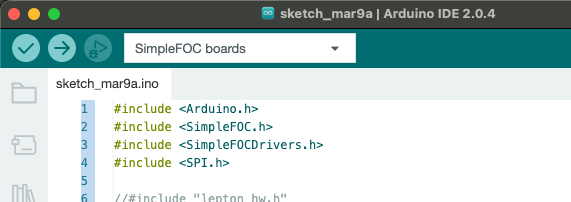

This is compiling for me now.
The problem is, unlike with PlatformIO where I can share a project containing everything needed for a new board to github, and you can just download and use that project, for ArduinoIDE this stuff happens in the platform files.
So I’m actually unsure how to get it to you. Short of sending STM32duino a pull-request, them merging it, and you waiting for the next platform release, it seems that everything else is going to be some kind of kludge. ![]()
If anyone has any suggestions I’d love to hear them. I’ll also ask the stm32duino people if there is a method…