Hi, I’ve searched in this forum, and I understood pwm input has not been implemented, and I think it is because that’s not efficient.
but, some cheap brushless motor like this iPower GM series come with a AS5048A encoder, and a PWM output cable only.
I’ve tried to solder SPI cables to it, because it is not easy to find those 6 poles - 1mm pitch connectors, and I had success in soldering, while I had bad results in reading data… (latest library version, 2.02 I think)
So, what’s the problem in reading a pwm input? maybe the lack of a spare timer?
Lack of spare time ![]()
We would really like to support it but we just don’t seem to find the time to do it ![]()
But we are very much open to collaboration!
The biggest problem is not really the resolution but the timings. They usually have pwm clock of 1khz which means that you will have the angle update each millisecond. This is not really good for high velocity and smoothness, but it will work. And we will implement it soon I hope ![]()
You should be able to have good results with the SPI communication, people have already used these senors with the library. I am sure there are people here who can help ![]()
I can try to implement that. I know about the millisecond refresh time, but for a lot of simple cases it could be just fine.
Can you just tell me which timers are already busy?
I’ll open another thread for my spi problems. before asking I would like to do some more check.
If you have time that would be great! You can use the ‘MagenticSesnor*.cpp’ as template, this one will not be too much different. 
In my opinion the simplest option would be the interrupt routine called by the pin the pwm is attached to. And then the interrupt will count the microseconds in between the calls ( _micros() function).
And sensor can have optional function sensor.attachInterrupt(callback) or people can use PciManager or similar libraries.
Does this sound reasonable, what do you think?
I have to do some testing, because I don’t know if the PWM output has also 14 bit of resolution.
in that case microseconds are not enough. But if I think this is aimed to a simple use, just using uS resolution gives us a 1000ppr of resolution, which is honestly good enough. So I agree with you.
in the meantime I understood why it didn’t work using SPI. The problem was the general constructor which uses these values:
command_parity_bit = 15; // for backwards compatibilty
command_rw_bit = 14; // for backwards compatibilty
data_start_bit = 13; // for backwards compatibilty
while I wrote a special constructor like this:
/** AS5048_SPI*/
MagneticSensorSPIConfig_s AS5048_SPI = {
.spi_mode = SPI_MODE1,
.clock_speed = 1000000,
.bit_resolution = 14,
.angle_register = 0x3FFF,
.data_start_bit = 14,
.command_rw_bit = 14,
.command_parity_bit = 15
};
which works great!
Please Antun, can you add that to the source?
I think it can be a nice thing to add pwm compatibility because not so many people are going to solder into 1mm pitch pads…
1 Like
Yes with pleasure!
At the moment you can use the AS5147_SPI which has the same parameters. But you’re right that it is confusing!
You are absolutely right. But adding an additional timer will make very complicated Arduino code. I would make initial simple support and if people are not happy with it we can always make it better.
The same is true for MagneticSensorAnalog which is not optimal in any way ![]()
This whole library is somehow more meant to enable then to optimize ![]()
Unfortunately no, the .data_start_bit is 13 instead of 14, that’s why I added another configuration.
in my case it didn’t work using 13, but it would be great if other people could confirm that.
To be precise the chip used here is AS5048L always AMS apart from the fact that it is not mentioned in any datasheet. maybe there could be some tiny difference…
I had time to do some tests…
I used this code, with PWM read on pin 2 to use arduino interrupts:
#define pinPWM 2
volatile unsigned long _mic, time_passed, time_now, period_time_passed, period_time_now;

void setup() {
  Serial.begin(115200);
  pinMode(pinPWM, INPUT);
  attachInterrupt(digitalPinToInterrupt(pinPWM), pwm_callback, CHANGE);
  delay(1000);
}

// min 8
// max 930

void loop() {
  if (period_time_passed > 950) period_time_passed = 950;
  //Serial.println(period_time_passed);
  //Serial.print(",");
  Serial.println(map(time_passed, 8, 930, 0, 359));
  delay(1);
}

void pwm_callback() {
  if (bitRead(PIND, pinPWM) == 1) {
    time_now = micros();
  } else {
    _mic = micros();
    period_time_passed = _mic - period_time_now;
    period_time_now = _mic;
    time_passed = _mic - time_now;
  }
}
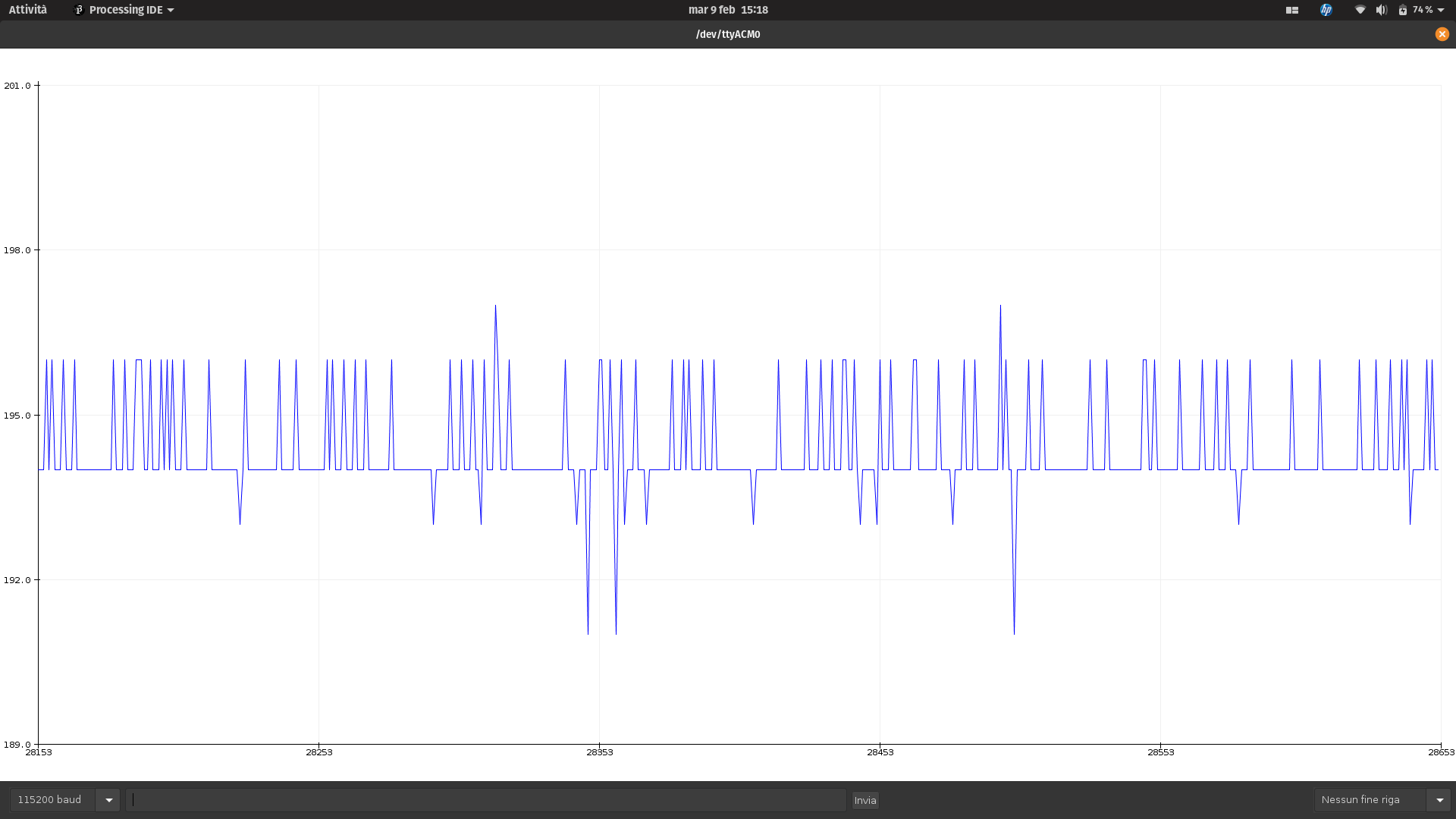
It kind of works, but even if I translate 8-930 range to 0-359 angle range, I see the value continuosly jumping ± 2° or 3°. which is too much for any kind of control…
Maybe we can try the timer way, to gain in precision, but honestly I feel it is not worth trying…
These are screenshots taken to see what comes out reading the range 0-359 as output.


OK, noted!
Thanks for the code, I’ll look into it, maybe we can include some filtering.
I’ll try to implement it to test ![]()
I’m so sorry Antun, I have to correct myself! really don’t know how it happened, but it is correct with .data_start_bit = 13, not 14.
So, the configuration for AS5048L is the same of AS5147…
Again, sorry for all this confusion.
Ok, noted! 
I’ll make sure to add the structures with same names as the sensor classes to avoid confusion.
Hey - so cool that you tried this out!
The PWM resolution is only 10bit, but that should still mean a position accuracy of around 0.35°…
I wonder why it is jumping so much? I have to say though, I think interrupts might be the wrong way to go… with more than 1000 interrupts/sec your chip will be quite busy just counting edges. And other interrupts (serial port, etc) might interfere with the accuracy. Maybe it needs to be on a counter-pin that can handle it in hardware?
Anyway, I had exactly the same issue with those cheaper AS5048A encoders - SPI pins too hard to solder…
Hey @runger,
It’s pretty inefficient way I agree
But i just wanted to put 1000 interrupts in the context of encoder interrupts.
Arduino UNo actually supports relatively robustly up to 20000 interrupts per second.
For esp, stm and the other 2000 is a pache of cake
But i agree it is not the best way to handle this.
You are right, of course. Even a venerable ATMega would have 16000 cycles for each 1kHz PWM cycle. And on the ESP32 it would be 240000 cycles - so quite comfortable head-room.
And the PWM signal is 12 bit, not 10 bit.
Still, I wonder why it was so inaccurate. After all, that type of setup is used for Gimbals pretty commonly, and I don’t think they’d get away with 3% angle error.
It seems PWM magnetic sensors are now officially supported. Am I right?
I’m asking because:
- I’m a newbie here so I need to be reassured
 , and
, and - I noticed that, although there are now
MagneticSensorPWMfiles in src/sensors:- those files are not included in the
Minimallib version, and - the Connecting the hardware page says nothing about PWM sensors.
- those files are not included in the
Yes, we now have support!
The standard support uses the micros function, and unfortunately this is not very accurate.
There is also timer-based support, for some architectures (STM32 I think). See a recent thread on this here:
https://community.simplefoc.com/t/low-speed-bldc-issues-jittery-movement/966/8
All in all, I’d say this is still quite new (hence undocumented, sorry about that!) and you should expect a few troubles if you decide to try it out…
Yep, the support is there, but it is true that these sensors have the worst performance over all the other sensors supported by the library. They can be used but there might be some issues depending on your hardware.
But the rule of thumb is, don’t use atmega328 or atmega2550.
The PWM sensors are in docs though
The minimal branch is out of date at the moment. But the ide stays the same and you ca just copy the code of the library src folder to the library_source and then do the same procedure as described in the readme.
Well try to update the minimal branch soon.
Ok, that’s great, thanks.
Given all the warnings, I will rewire my sensor in SPI.
The missing doc is in the SimpleFOCShield part (how to connect).
Thanks again.