Wow, a whole day without a new post on the board. Getting bored.
It’s mosquito season here in California, the recent rain brought up the larvae and they just started hatching. This, and me very recently finding a really cheap Chinese knockoff of DRV8313 on JLC, which is in stock, inspired me to create a small board, which may or may not work but was fun to do.
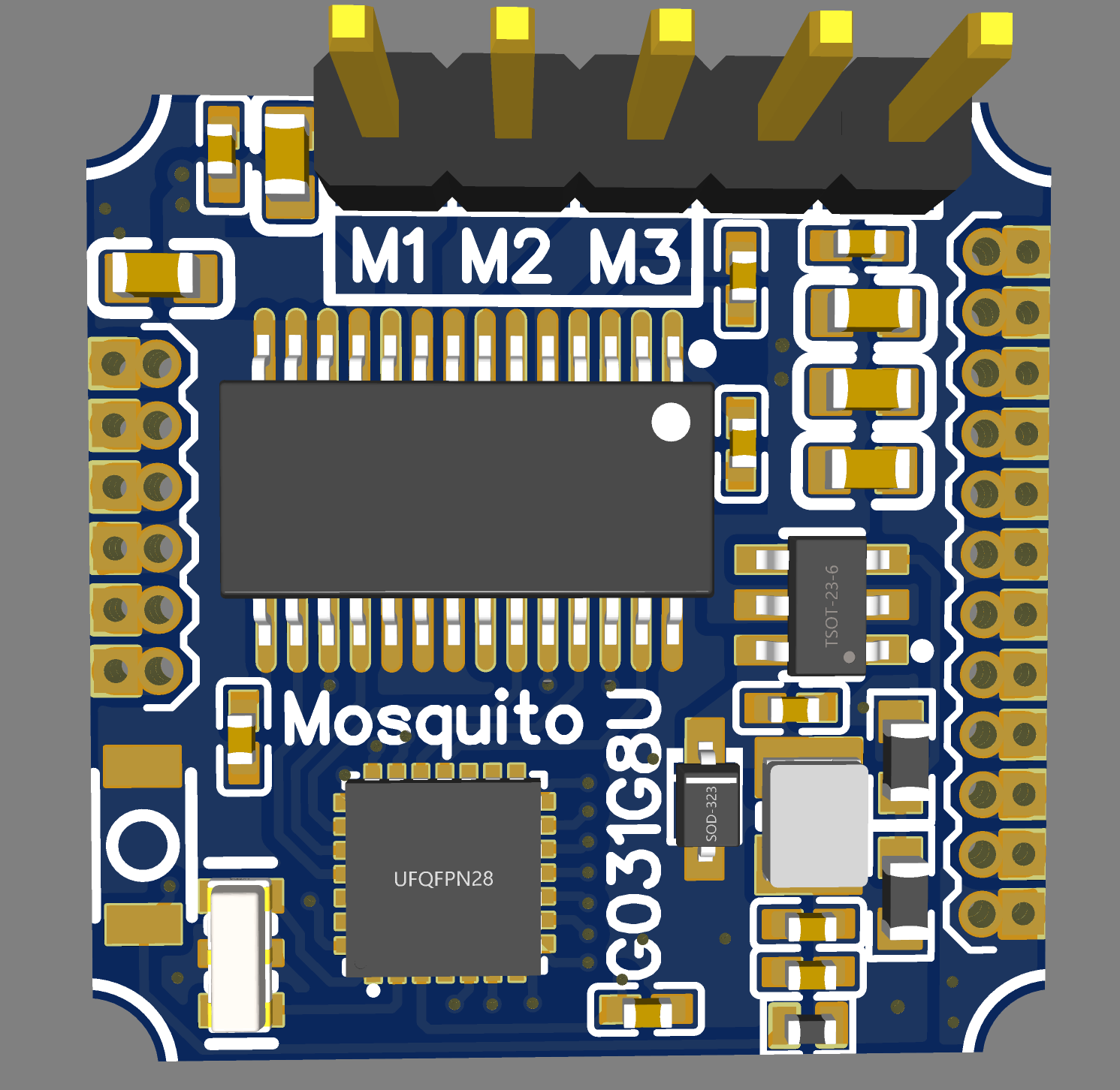
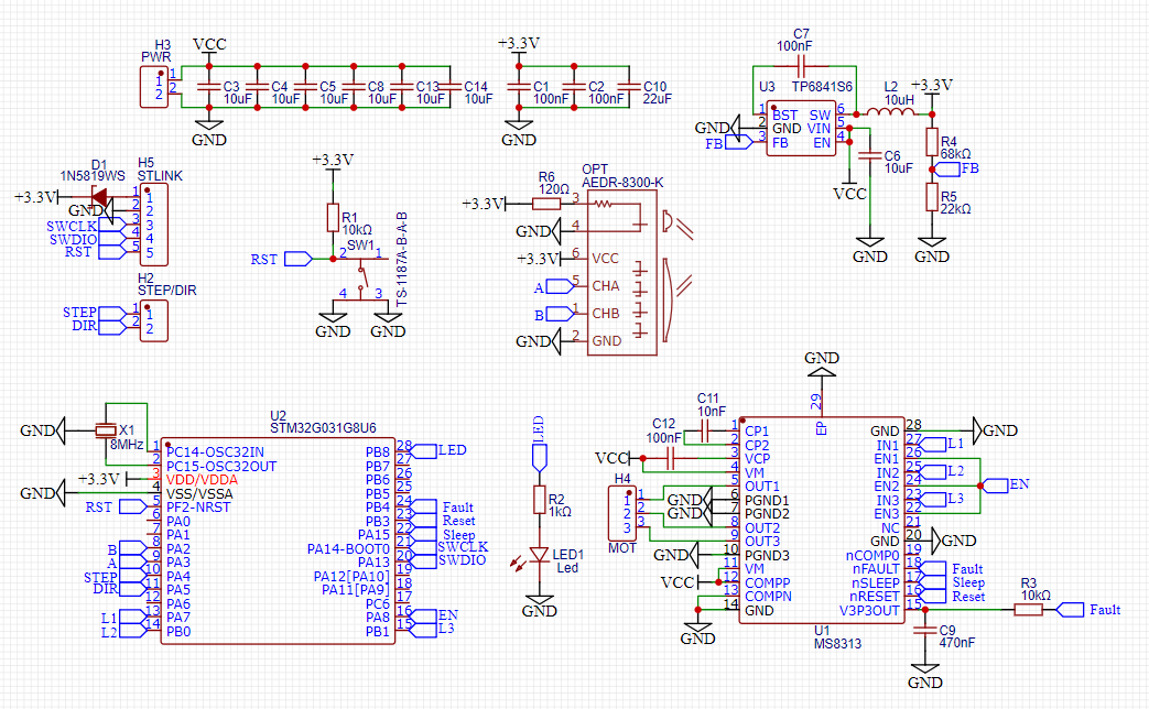
Board is fully integrated G031 with the DRV8313 knockoff, size 20mm x 20mm.
Well, good news. The board works! Actually it works a bit better than I thought. There are kinks to be ironed out and some work to make it more end-product-like but you can program the tiny MCU and driver and turn a decent 50mm size gimbal. I’m sure there will be many issues mostly with figuring out which pins do what and what really could be programmed with Arduino, however, this is so far looking up. At 20mm X 20mm with an integrated angle sensor this is the smallest, Arduino programmable, completely self-contained SimpleFOC bldc tiny board!!!
Again, this is a hobby effort so there is absolutely no promise when I’ll get the time to finish this side show.
Also, I’m not opening the design until I confirm that the end production-like board works end to end. It may be some time.
In addition, you can simply replace the cheap chinese driver in the BOM with DRV8313 (also in stock) and output 3A up to 60V, IIRC. That’s quite good. It will add only $1 to the board.
This looks very interesting, nice work.
I would like to use the same combination of STM32 + DRV8313 for a project (gimbal motor <0.5A).
Since im not the best programmer, is the STM32G031G8 straightforward to use with arduino?
Can i just select the “Generic G031K8Tx” , since the 28pin - G031G8 package is not directly supported?
Does that work?
Thx,
Greetings
David
You mean you want to use the Mosquito board or you are developing your own hardware solution?
Yes. However, this G031 MCU uses connect under reset and requires the use of SWD debugger as well as the external Cube programmer, else Arduino cannot connect directly. Writing the code should be just another Arduino code, but programming this MCU (I mean loading the binary) is very tricky if you haven’t done it.
It’s doable, yes. If you are stuck let me know I could walk you through it.
Thx
I wanna use my own board with more or less the same components,
For my project i just need a step/dir input and an AB encoder (AEDR-8300).
The pcb should be small and light, so the G031G8 comes in handy.
And the G031G8 is one of the few MCUs in stock at a reasonable price.
I already have a ST-Link V2 to flash it.
Sry, i dont wanna hijack your thread for my project.
Greetings,
David
That’s really nice. I like the selection of the components, especially the integrated resonator and the step-down buck converter. Got a few questions if you don’t mind. Perhaps you have already resolved these, but just in case.
You are using B3, B4 and B5 for PWM. They are connected to different timers. This will be a problem, because your timings will be off. Have you considered this? I mean, have you tested that the timings are correct on a G031 breakout development board?
You are connecting SLEEP and RESET to V3P3OUT pin. This means you cannot put the board to sleep, nor can you reset the board in case after a fault. What cases / use scenarios the board is running which will prevent the board from reset and resume normal operations after a fault? Do you manually unplug the power?
The MCU decoupling capacitor is really far, behind the resonator, wouldn’t that destabilize the MCU power? It’s very hard to tell but I think you even put the power through vias which will adversely increase impedance even more. Or, may be that black thing next to it is a capacitor, I cannot tell, in which case you don’t really decouple because you route the power through a via directly into the MCU.
That’s a really nice render. Do you 3D print everything or you buy the whole thing and only design the PCB? Did you design the housing yourself?
Please ignore my questions if you don’t have time, I’m only curious.
I pulled Sleep and Reset HIGH, because i thought i wont need it, since the 3d Printer controller can just send the step/dir signals and nothing more, but now i connected them to the MCU, so i am more flexible.
Also the fault pin.
Sadly i dont have a G031 development board.
Thanks for mentioning the PWM pins (Timer) , i forgot to check that
Now all are on timer1 (ch1-3).
I also moved the MCU cap as close as possible to the MCU.
Designed all by myself with fusion 360 and made it with my CNC and 3D Printer.
Its already working with a 32f103 and L298 + AEDR8300.
I was a bit tricky to get the encoder working, but once i figured it out it worked perfectly.
Thats just a polished stainless steel disc engraved with a PCB carving bit. (150cpr)
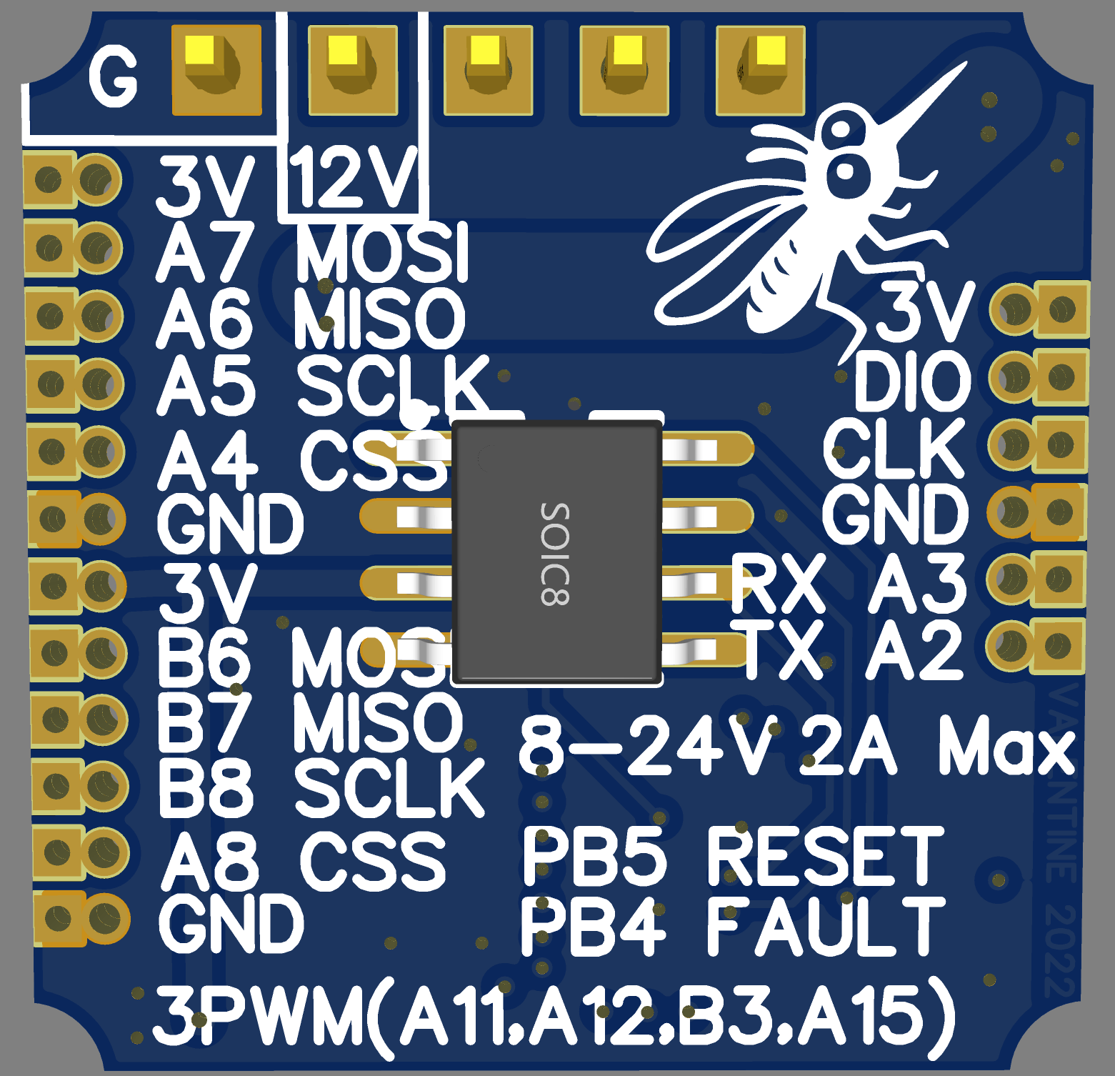
New schematic and board:
The actual thing:
Best Regards,
David
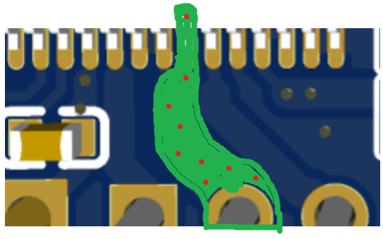
If you don’t mind, a few comments on the PCB layout. Not a criticism, just minor observation:
You may need a via right here
to prevent an “antenna icicle” effect. The two lines around and the ground pour sticking like that forms an 8MHz antenna which emits at different frequencies the way it’s formed. Essencially it becomes a fractal antenna.
Create direct surface connections for the PWM which are the timing critical tracks and route the enable under with a via.
Essentially route first the critical PWM connections to avoid impedance signal distortion, then route the enable, etc which are non-critical and could have vias, high impedance, etc.
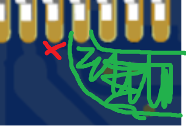
Check how I’ve done it on my macro photo above. It’s exact opposite of how you’ve done it.
Non-critical, but consider creating copper plates instead of using tracks here
This will allow for proper high-current path of the phase output to the pins. Since in your case you will be drawing low power it’s not really critical but it’s a good practice to have and then use vias to route on multiple layers to increase the effective copper surface and current carrying capability. That one is extremely tricky if you haven’t done it before. Chek again my photo:
Route the ground pin to the back ground pour plate and use again a copper plate to feed the input voltage to increase current carrying capability. See again that above.
Post pictures of the board once you are done. Excellent job.
Let me try and program G031 myself and see if your timers pin choice will work else you will end up with a pretty artwork to hang on the wall as a souvenir. Give me a few hours, I’ve got some other things to do. Hopefully you see this before you order
Have you programmed G031 before? What tool chain are you using?
Thanks man, thats very kind
I never had a G031G8 in my hands
For the Bluepill i used mostly Arduino and stlink directly.
But i also tried it with the exported Bin code from arduino
and the STM32CubeProgrammer + Stlink, which worked too.
The same method should work for the G031G8 i hope.
So, the boards arrived, and i already made a mistake.
I strapped the comp+ pin of the MS8313 high because im used to do that from other circuits.
But i forgot to check the max voltage for it. Lets say 12V was to much.
So i lost the 1st board. But the 2nd works pretty well,
nothing gets hot, not even warm, flashing is no problem.
Just the programm, it only works partially.
But for that i´ll open a separate thread.