# How do I add SimpleFOC support to my "SimpleBLDC" controller?
**URL:** https://community.simplefoc.com/t/how-do-i-add-simplefoc-support-to-my-simplebldc-controller/7184
**Category:** hardware support
**Tags:** bldc, arduino
**Created:** [May 13, 2025, 11:16pm UTC](https://community.simplefoc.com/t/how-do-i-add-simplefoc-support-to-my-simplebldc-controller/7184 "2025-05-13T23:16:34Z")
**Posts on this page:** 8
**Page:** 1
### Author:  [@Techn0man1ac](https://community.simplefoc.com/u/Techn0man1ac)
#### Post date: [May 13, 2025, 11:16pm UTC](https://community.simplefoc.com/t/how-do-i-add-simplefoc-support-to-my-simplebldc-controller/7184/1 "2025-05-13T23:16:35Z")
Hello, community.
As a hobby, I am [developing a simple BLDC controller](https://github.com/techn0man1ac/SimpleBLDC) for an electric bicycle (motor wheel, direct drive, with Hall sensors) for 650 watts, I have already developed the hardware, ordered, assembled. Now it’s time to write the firmware.
I’m new to this topic, so please tell me how to adapt SimpleFOC to my circuitry?
Thank you.
---
### Author:  [@dekutree64](https://community.simplefoc.com/u/dekutree64)
#### Post date: [May 14, 2025, 9:33am UTC](https://community.simplefoc.com/t/how-do-i-add-simplefoc-support-to-my-simplebldc-controller/7184/2 "2025-05-14T09:33:56Z")
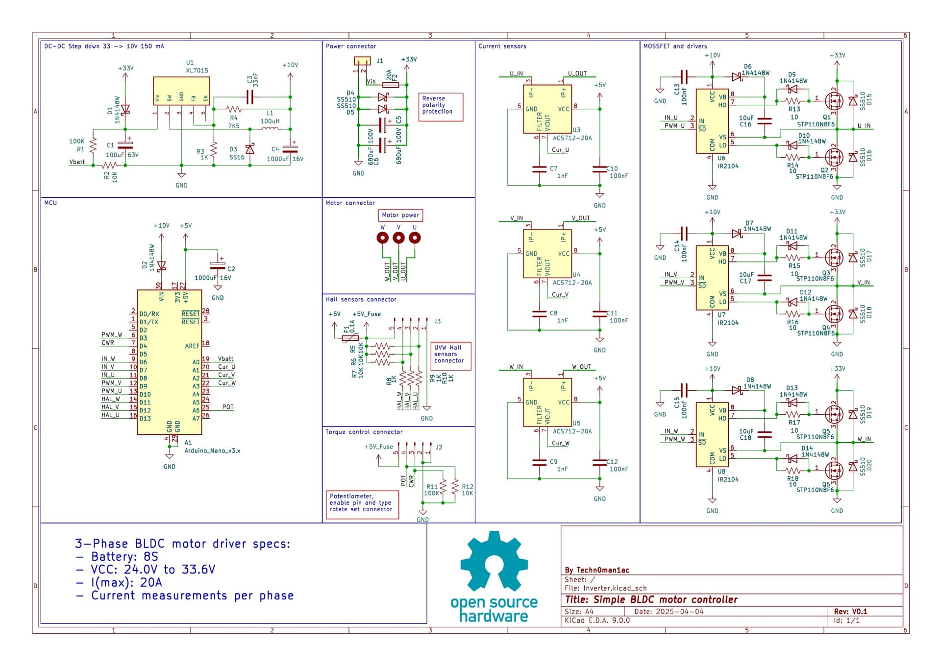
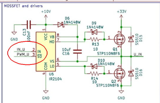
Looks like it should be effortless, just passing the appropriate pins to BLDCDriver3PWM, HallSensor, and InlineCurrentSense. However I think you made a mistake in the driver wiring. The IN\_x pins are connected to the driver PWM inputs, and PWM\_x pins are connected to driver enable/disable. Unfortunately D7 and D8 can’t do PWM, so you’ll have to fix it.
---
### Author:  [@dekutree64](https://community.simplefoc.com/u/dekutree64)
#### Post date: [May 14, 2025, 12:47pm UTC](https://community.simplefoc.com/t/how-do-i-add-simplefoc-support-to-my-simplebldc-controller/7184/7 "2025-05-14T12:47:12Z")
> [@](#):
>
> Are you talking about this? [3.2 Six-Step (Trapezoidal) Commutation](https://onlinedocs.microchip.com/oxy/GUID-ED5A4EC0-70D9-40E8-82A4-9EE711C91C4E-en-US-11/GUID-A2E50F02-E898-425F-B2A2-36E161DE810B.html)
Yep. The two active phase’s input pins would be set according to which is driven positive and negative. You would set the “not driven” phase’s PWM duty to 0, so the value of its input pin is irrelevant. The other two could either have equal PWM duty to control the power level, or one set to 100% and the other variable. The result would be the same either way since no current can flow unless at least two phases are on.
> [@](#):
>
> To be honest, I was inspired by the circuitry on the M365 e-scooter board. [M365 motor controller - how to get running?](https://community.simplefoc.com/t/m365-motor-controller-how-to-get-running/5293)
That’s a different driver with separate input for each mosfet. It would use the BLDCDriver6PWM class. Yours have a single PWM input, so would use BLDCDriver3PWM if it were wired properly. The end result is more or less the same, just different ways of going about it.
---
### Author:  [@Techn0man1ac](https://community.simplefoc.com/u/Techn0man1ac)
#### Post date: [May 14, 2025, 9:53am UTC](https://community.simplefoc.com/t/how-do-i-add-simplefoc-support-to-my-simplebldc-controller/7184/3 "2025-05-14T09:53:50Z")
Schematics:
---
### Author:  [@Techn0man1ac](https://community.simplefoc.com/u/Techn0man1ac)
#### Post date: [May 14, 2025, 9:54am UTC](https://community.simplefoc.com/t/how-do-i-add-simplefoc-support-to-my-simplebldc-controller/7184/4 "2025-05-14T09:54:49Z")
Real photo my board:

---
### Author:  [@dekutree64](https://community.simplefoc.com/u/dekutree64)
#### Post date: [May 14, 2025, 10:34am UTC](https://community.simplefoc.com/t/how-do-i-add-simplefoc-support-to-my-simplebldc-controller/7184/5 "2025-05-14T10:34:06Z")
This is what I’m concerned about. You’re PWM’ing the shutdown pin, which disables both mosfets. I think you could implement trapezoidal modulation that way, but you’ll have to write your own code for it because SimpleFOC’s is written for the normal wiring where PWM goes to the input pin which controls which mosfet to activate.
---
### Author:  [@Techn0man1ac](https://community.simplefoc.com/u/Techn0man1ac)
#### Post date: [May 14, 2025, 11:30am UTC](https://community.simplefoc.com/t/how-do-i-add-simplefoc-support-to-my-simplebldc-controller/7184/6 "2025-05-14T11:30:23Z")
To begin with, I wrote a very primitive code (available in the repository) that simply switches the transistors in the half-bridge one by one.
This code reduces the CPU’s operating frequency from 16 to 8 MHz and thus the PWM frequency of 16.25 kHz, which was my goal.
With PWM, I limit the phase current to 0.7 A.
As a concept, it works, but the motor makes some strange noises(add English subtitles):
[ ](https://www.youtube.com/watch?v=uCgfCZ9AMLY)
---
### Author:  [@Techn0man1ac](https://community.simplefoc.com/u/Techn0man1ac)
#### Post date: [May 14, 2025, 10:50pm UTC](https://community.simplefoc.com/t/how-do-i-add-simplefoc-support-to-my-simplebldc-controller/7184/8 "2025-05-14T22:50:58Z")
I need help from the community to adapt SimpleFOC for my project.
Are there any video tutorials or articles on how to get started, any basic tests or settings?