# High power DRV8302 board support - 15A
**URL:** https://community.simplefoc.com/t/high-power-drv8302-board-support-15a/32
**Category:** hardware support
**Tags:** drv8302
**Created:** [July 3, 2020, 2:04pm UTC](https://community.simplefoc.com/t/high-power-drv8302-board-support-15a/32 "2020-07-03T14:04:00Z")
**Posts on this page:** 9
**Page:** 2
### Author:  [@rafaobrs](https://community.simplefoc.com/u/rafaobrs)
#### Post date: [February 22, 2022, 8:57pm UTC](https://community.simplefoc.com/t/high-power-drv8302-board-support-15a/32/21 "2022-02-22T20:57:00Z")
This FNB43060T2 seems to be exactly what I need. It maybe overkill and need some extra discrete components when compared with L6234, but it will be a lot more simple than our current schematics. I will do some research and buy it. When I test it I will post the results. Thank you!
---
### Author:  [@Valentine](https://community.simplefoc.com/u/Valentine)
#### Post date: [February 22, 2022, 10:55pm UTC](https://community.simplefoc.com/t/high-power-drv8302-board-support-15a/32/22 "2022-02-22T22:55:26Z")
> [@rafaobrs](#):
>
> maybe overkill
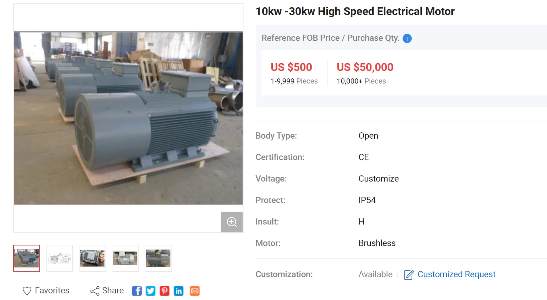
They are designed for 30kW industrial BLDC motors. Overkill is an understatement.
Please come back and post the design. Many people would be very happy to see the experimental setup. Hopefully it will look like something like the one below!
---
### Author:  [@cesare76m](https://community.simplefoc.com/u/cesare76m)
#### Post date: [September 10, 2022, 7:58am UTC](https://community.simplefoc.com/t/high-power-drv8302-board-support-15a/32/23 "2022-09-10T07:58:12Z")
Hi, i’ve this board, but i think that it has some problems, how can i test it?
---
### Author:  [@Valentine](https://community.simplefoc.com/u/Valentine)
#### Post date: [September 10, 2022, 12:51pm UTC](https://community.simplefoc.com/t/high-power-drv8302-board-support-15a/32/24 "2022-09-10T12:51:16Z")
You provide very little information.
---
### Author:  [@Hugop](https://community.simplefoc.com/u/Hugop)
#### Post date: [January 21, 2025, 9:12am UTC](https://community.simplefoc.com/t/high-power-drv8302-board-support-15a/32/25 "2025-01-21T09:12:39Z")
Hi! I have the same hardware: a DRV8302 board, and I would like to use the 3 AD8605 current amplifier circuits. It was mentioned in the thread that the gain is supposedly 12.2, but I am getting different results. When I connect the output of a current amplifier to an STM32 ADC, I measure a gain of more than 100 when passing some current through the MOSFETs.
To test, I am using a lab power supply and a load (a motor). I send a PWM signal to one half-bridge (Phase A), set the other half-bridge to low (Phase B), and disable the last half-bridge (Phase C). To calculate the current from the ADC reading, I subtracted the offset (2048 for a 12-bit ADC) and then obtained the voltage. However, the result is more than 100 times the voltage across the 5mΩ shunt, while it should be around 12.2 times more.
I have checked the components on the dev board, and they all match the schematic uploaded above. Additionally, I am applying a 1.65V reference. I cannot figure out what might be wrong. I understand that the power supply current indicator might not be very precise, but the discrepancy is far too large.
Thank you in advance for your help.
Best regards!
---
### Author:  [@Backflip](https://community.simplefoc.com/u/Backflip)
#### Post date: [May 10, 2025, 10:16am UTC](https://community.simplefoc.com/t/high-power-drv8302-board-support-15a/32/26 "2025-05-10T10:16:43Z")
> [@Antun\_Skuric](#):
>
> The current control loop is not implemented at the moment, but I have it very high in my list of priorities. So the next release of the _SimpleFOClibrary_ should have this feature.
I have been looking for a driver for a 24 VDC supply and about 12 Arms and 35 Apeak (short term). Then I noticed this driver board published five years ago, and it is still being sold from Aliexpress for about 40 Euro.
It seems that 6PWM is required from the MCU, so time delays needs to be implemented in software and hardware to avoid cross conduction of the half bridges. Furthermore three low-side shunts are used for measurement of currents.
Do the SimpleFOC software supports this?
Do you recommend some other driver with current sensors for this power range?
---
### Author:  [@Antun\_Skuric](https://community.simplefoc.com/u/Antun_Skuric)
#### Post date: [May 19, 2025, 5:26am UTC](https://community.simplefoc.com/t/high-power-drv8302-board-support-15a/32/27 "2025-05-19T05:26:32Z")
Hi @Backflip,
Yes, simplefoc implements everything that you need for this board:
- 6pwm or 3pwm - which can be configured
- low-side current sensing
- Multiple architectures: ex. stm32, esp32, teensy
You can even find some examples in the libraries examples folder.
[examples/hardware\_specific](https://github.com/simplefoc/Arduino-FOC/tree/master/examples/hardware_specific_examples/DRV8302_driver)
---
### Author:  [@Backflip](https://community.simplefoc.com/u/Backflip)
#### Post date: [May 19, 2025, 12:02pm UTC](https://community.simplefoc.com/t/high-power-drv8302-board-support-15a/32/28 "2025-05-19T12:02:25Z")
Thanks for the answer and link.
I have noticed the limit in measured current to be +/- 27 Amp, and I think this value is low. I have hoped for something like +/- 45 Amp. The power components should manage such peak currents short term. Of cause it is possible to change six resistors to achieve this.
---
### Author:  [@galileo](https://community.simplefoc.com/u/galileo)
#### Post date: [September 18, 2025, 8:54pm UTC](https://community.simplefoc.com/t/high-power-drv8302-board-support-15a/32/29 "2025-09-18T20:54:56Z")
Thanks Antun
I’m trying to run a DRV8302-based board with a Teensy 4.1 using low-side current sensing, but I’m running into problems while following the documentation for `TorqueControlType::foc_current`.
**Setup**
- MCU: Teensy 4.1
- Driver: DRV8302
- Motor control pins:
- Current sense pins:
**Problem**
The function `_configure3PWM()` was returning `nullptr` for `TeensyDriverParams.additional_params`.
This caused `_configureADCLowSide()` in `LowsideCurrentSense::init()` to fail with:
```auto
SIMPLEFOC_CURRENT_SENSE_INIT_FAILED
```
**Workaround Attempt**
I modified `_configure3PWM()` to initialize `Teensy4DriverParams` manually:
```auto
Teensy4DriverParams* additional_params = new Teensy4DriverParams;
additional_params->flextimers[0] = &IMXRT_FLEXPWM2; // Pin 4: SM0/ch0
additional_params->flextimers[1] = &IMXRT_FLEXPWM2; // Pin 5: SM1/ch0
additional_params->flextimers[2] = &IMXRT_FLEXPWM2; // Pin 6: SM2/ch0
additional_params->submodules[0] = 0;
additional_params->submodules[1] = 1;
additional_params->submodules[2] = 2;
additional_params->channels[0] = 0;
additional_params->channels[1] = 0;
additional_params->channels[2] = 0;
additional_params->dead_zone = 0.0f;
TeensyDriverParams* params = new TeensyDriverParams{
.pins = {pinA, pinB, pinC},
.pwm_frequency = pwm_frequency,
.additional_params = additional_params
};
```
**Result**
The build now succeeds, and `cs.init()` no longer fails.
However, during sensor alignment the motor does not move. Debug output:
```auto
MOT: Monitor enabled!
MOT: Init
MOT: Enable driver.
MOT: Align sensor.
MOT: Failed to notice movement
MOT: Init FOC failed.
```
**Question**
What am I missing in the Teensy4 driver setup for low-side current sense with DRV8302?
Thanks,
Gal
[Previous page](https://community.simplefoc.com/t/high-power-drv8302-board-support-15a/32.md?page=1)