Hi
Since you are already deep into the lib, I just want to ask a question regarding position/angle control precision using 3 Hall sensors at 120 degrees. The magnets are 3mm long and it’s a 14/12 configuration (linear)?
I’m asking this because I wonder if a external encoder will be needed.
Best regards
On my hoverboard motor i think i worked out the precision to be 1 tick = 4 degrees.
You get 6 states per electrical revolution
From memory the states for the 3 magnets are like this:
A B C
0 0 1
1 0 1
1 0 0
1 1 0
0 1 0
0 1 1
The halls are typically attached to the stator and are sensing the magnetic pole pairs moving past them. So in the case of my hoverboard motor that has 30 magnets and therefore 15 pole pairs, we have 15 electrical revolutions per shaft revolution. As each electrical revolution has 6 states I have 90 ticks per shaft revolution. Hence 360/90=4 degrees per tick.
I don’t know exactly what you mean by a linear motor. I presume its a normal motor with a worm gear or similar. You say 14/12 configuration. Is this slots pole/pairs or gear ratio?
Lets say your motor is a 12n14p (12 slots 14 magnets) then it has 7 pole pairs. So running the same maths is going to give you 42 ticks per rotation. You’ll have to convert that to linear distance.
Does your motor already have halls fitted? Given a choice I’d go for a magnetic encoder. These often have 16k ticks per revolution. A cheapo as5600 (£3 on ebay) has 2k ticks per revolution. Gluing a diametric magnet to the back of the motor and 3d printing something to hold the sensor isn’t too difficult but if you don’t have a printer…
Ok, thanks for that clarification.
By linear i mean tubular. 3mm round magnets inside a tube, with the coils around. Ironless.
So having 7 magnets (14 polepair, since the magnets use north and south pole) 3mm x 7 + spacers = around 30mm / 42 ticks. Circa 0,7mm precision. With tuning, maybe it could be smoothed out.
Actually i was thinking, if there is a way to measure the magnetic force instead of the On/off state. Like a analog output, which potentially could yield much better precision ?
Edit: Kinda like these Hall sensors : https://sensorso.com/ah.html
The board has the HALL´s fitted… on the backside.
Here is a potential Linear Analog HALL sensor: https://www.ti.com/lit/ds/symlink/drv5053.pdf?HQS=TI-null-null-mousermode-df-pf-null-wwe&ts=1602339685917&ref_url=https%3A%2F%2Fwww.mouser.dk%2F
With these sensors, potentially, you get the ADC resolution per polepair.
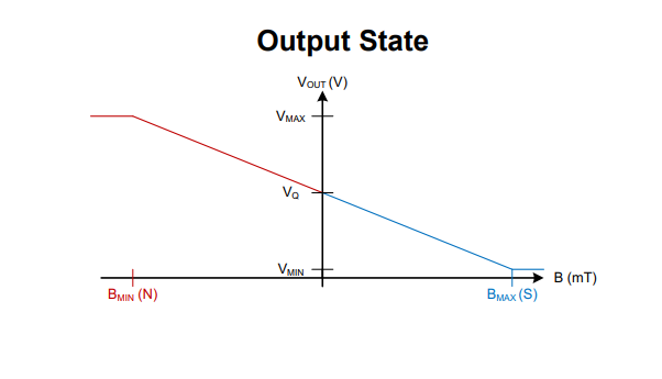
Analog sensors may not work very well due to the stator coil field contributing to the value you read. The permanent magnets seem to be enough stronger that it’s not an issue with on/off sensors, but I’m not sure about analog.
But it should be possible to do microstepping similar to how stepper drivers do, using PWM to position the stator field inbetween two sensor states.
Ok, so maybe if the hall´s is sitting inside the motor there could be some issues, but i do not plan for the board to be inside the motor. The coils will be above or below the board, and the underside of the board (where the HALL sensors are) will be sliding over the magnets with X distance.
Edit: I do see your point. But from the perspective of a linear setup, as long as you have some distance to the coils, it will work.
1 Like
@Owen_Williams
Regarding precision,
Is the 3 phase bldc running FOC able to “half step” / apply torque until the rotor moves into position.
Specifically, I am thinking of a motor with 190kV running on a 24v PSU. The no-load rpm would be 4560rmp (76 rotations per secund). If I put a gearing on the shaft to increase the torque and reduce the rotations with 1:5. (76rps / 5 = 15.2rps). If our target speed is 1200mm sek. the pulley has to transport the gantry 1200/15.2rps = 96mm. The primary gear (shaft ) would have to turn 15.3rps * 5 = 76rps * 60 4560 rpm.
So if one rotation is 42 tics per revolution like you wrote earlier, and it takes the shaft 5 rotations to turn the pulley one rotation. 42tics x gearing(5) = 210 tics per revolution = 96mm / 210tics = 0.45mm per increment. Could you hit a target angle between two “tic´s”
Edid: Just found the calc sheet posted her : https://community.simplefoc.com/t/practical-simplefoc-limitations/364/12