# Experimental high-current driver -- 30A
**URL:** https://community.simplefoc.com/t/experimental-high-current-driver-30a/1481
**Category:** hardware support
**Created:** [December 17, 2021, 2:45am UTC](https://community.simplefoc.com/t/experimental-high-current-driver-30a/1481 "2021-12-17T02:45:39Z")
**Posts on this page:** 20
**Page:** 2
### Author:  [@MoidKhan](https://community.simplefoc.com/u/MoidKhan)
#### Post date: [January 14, 2022, 8:44am UTC](https://community.simplefoc.com/t/experimental-high-current-driver-30a/1481/21 "2022-01-14T08:44:25Z")
> [@Valentine](#):
>
> MCP14700-E/MF
Hi Valentine,
Nice design and work. If possible can you share the schematics? I am currently working on a project in which I am using DRV8302 Eval board, but that board size is very large and I want to make a compact BLDC motor driver board. The infenion Mosfets are great for my project but they are out of stock now. Do
---
### Author:  [@Valentine](https://community.simplefoc.com/u/Valentine)
#### Post date: [January 14, 2022, 1:23pm UTC](https://community.simplefoc.com/t/experimental-high-current-driver-30a/1481/22 "2022-01-14T13:23:06Z")
MCP are also out of stock. I will share once i confirm its safe.
---
### Author:  [@Valentine](https://community.simplefoc.com/u/Valentine)
#### Post date: [January 20, 2022, 3:50am UTC](https://community.simplefoc.com/t/experimental-high-current-driver-30a/1481/23 "2022-01-20T03:50:36Z")
> [@Valentine](#):
>
> will share once i confirm its safe
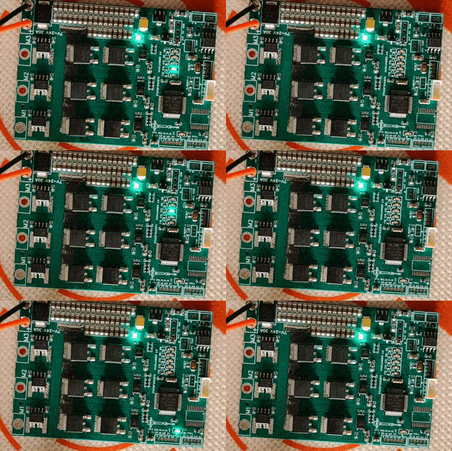
My HackJammer arrived, and tested the MCU and main power stage well.
These are GIF videos, you need to click on the run arrow depending on your browser if they don’t autoplay.
LED test
Motor test
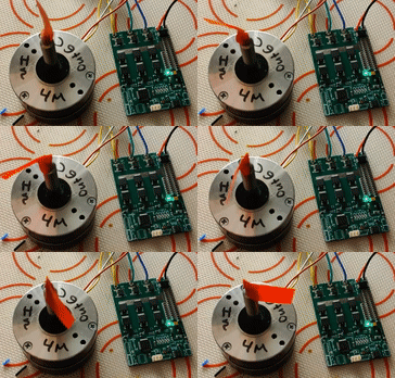
Wish I had the original MOSFETs in stock but at least I ended up testing another driver with that one, as well as different, very cheap generic mosfets.
I have not tested the current sense yet, as well as any of the I/O (CANBus, UART, etc).
I’m most concerned about the current sense, since I’m using a hall current sensor. 🤞 🤞 🤞
I’ll clean up the PCB and share it once it goes well.
@German_io , hope that works out for you.
---
### Author:  [@German\_io](https://community.simplefoc.com/u/German_io)
#### Post date: [January 20, 2022, 6:47am UTC](https://community.simplefoc.com/t/experimental-high-current-driver-30a/1481/24 "2022-01-20T06:47:40Z")
Looks great. I hope too. Thank you!
---
### Author:  [@German\_io](https://community.simplefoc.com/u/German_io)
#### Post date: [January 20, 2022, 7:41am UTC](https://community.simplefoc.com/t/experimental-high-current-driver-30a/1481/25 "2022-01-20T07:41:32Z")
Can you add some holes on PCB for holding it ?
---
### Author:  [@Valentine](https://community.simplefoc.com/u/Valentine)
#### Post date: [January 20, 2022, 2:29pm UTC](https://community.simplefoc.com/t/experimental-high-current-driver-30a/1481/26 "2022-01-20T14:29:16Z")
> [@German\_io](#):
>
> holes on PCB for holding it
Next version will have more end-product look. I’m still at testing stage.
---
### Author:  [@Valentine](https://community.simplefoc.com/u/Valentine)
#### Post date: [January 21, 2022, 1:23am UTC](https://community.simplefoc.com/t/experimental-high-current-driver-30a/1481/27 "2022-01-21T01:23:09Z")
> [@Valentine](#):
>
> current sense, since I’m using a hall current sensor
Current sensors are testing fine.
One of the phases however does not make it to the MCU correctly. The sensor generates the signal, however, there may be an issue with the voltage divider not being correctly soldered by JLC. The end lead does not carry the signal. Problem is, the track is buried, unless I X-Ray the board, can’t find out what’s wrong and the prospect of X-Raying that piece of copper is out of question.
This is a minor inconvenience, which will be resolved in the next iteration. I have another copy of the board to test, and perhaps increase the space to ensure correct solder, though its very surprising, usually JLC is pretty good at soldering the tiny resistors.
Other than that, the board so far looks really good.
Also, I see the CANBUs controller is back in stock.
Problem is, JLC goes into Chinese New Year and things won’t come back until beginning of February. They already started cutting down on orders.
@German_io , let’s hope nothing else unexpected comes up, but I’d up the chances of this board being successful to 80%. By my estimation, barring anything out of the ordinary, somewhere in March I’d release the final version.
Cheers,
Valentine
---
### Author:  [@German\_io](https://community.simplefoc.com/u/German_io)
#### Post date: [January 21, 2022, 8:20am UTC](https://community.simplefoc.com/t/experimental-high-current-driver-30a/1481/29 "2022-01-21T08:20:31Z")
Some good news at this difficult time. I think all will good.
---
### Author:  [@Valentine](https://community.simplefoc.com/u/Valentine)
#### Post date: [January 22, 2022, 9:29pm UTC](https://community.simplefoc.com/t/experimental-high-current-driver-30a/1481/30 "2022-01-22T21:29:28Z")
I continue testing, the current sensors are actually good. I may have been tired and measured the 3-rd phase on the wrong test lead.
Hall-based current sensor signal, can’t get any more perfect than that. Very clean.
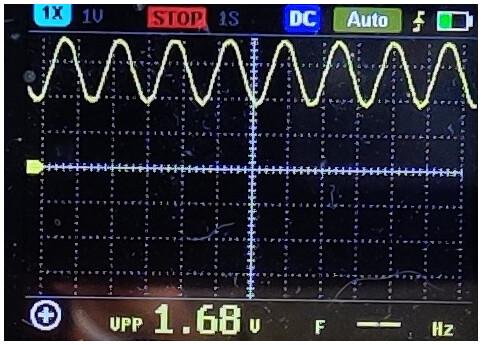
I’ll continue testing, so far all motors I tested performed well. At 30A the board got hot.
As already estimated, that board can’t carry over 30A. I mean, the cables and solder joints themselves got hot, the flux started to melt and smoke, haha. I’m using low-temperature lead-free solder, so not surprising.
The mosfets and sensors however behaved just fine. Hot but could be touched. That’s actually good news.
Over 5A needs heatsinks, and really good solder joints, thick cables, and well cooled environment. That’s not a hobby board.
---
### Author:  [@Valentine](https://community.simplefoc.com/u/Valentine)
#### Post date: [January 23, 2022, 12:43am UTC](https://community.simplefoc.com/t/experimental-high-current-driver-30a/1481/31 "2022-01-23T00:43:02Z")
> [@Valentine](#):
>
> continue testing, so far all motors
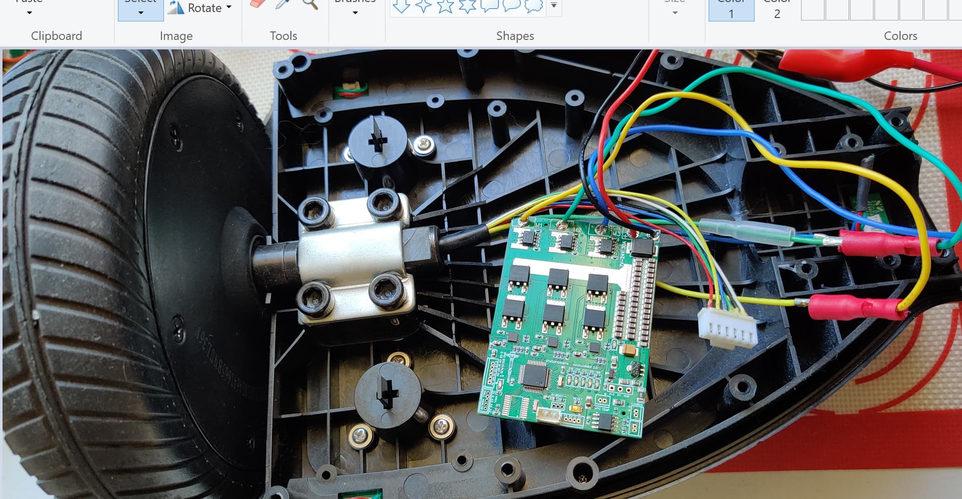
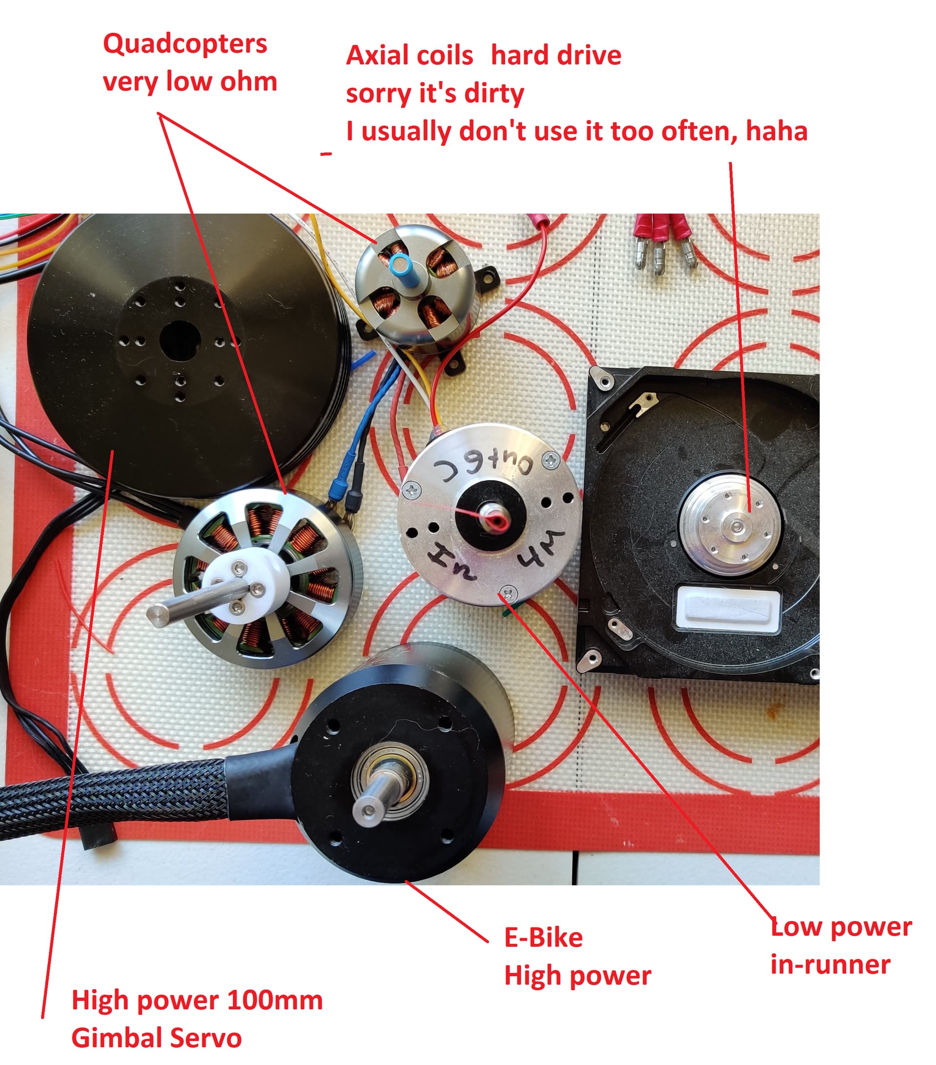
The motors I tested, open loop.
Hoverboard:
Other motors
---
### Author:  [@happytm](https://community.simplefoc.com/u/happytm)
#### Post date: [January 23, 2022, 1:26am UTC](https://community.simplefoc.com/t/experimental-high-current-driver-30a/1481/32 "2022-01-23T01:26:22Z")
Interesting to get Hoverboard motors working with SimpleFOC using your board.
---
### Author:  [@Valentine](https://community.simplefoc.com/u/Valentine)
#### Post date: [January 23, 2022, 1:31am UTC](https://community.simplefoc.com/t/experimental-high-current-driver-30a/1481/33 "2022-01-23T01:31:43Z")
@German_io
> **[Project - Platform for creating and sharing projects - OSHWLab](https://oshwlab.com/cost.co/20211214_bldc_ipt015n10n5_100v_300a_copy)**
>
> Whether you are sharing innovative hardware designs or finding design inspiration, this is the best place for you. From beginner to specialist, we can all communicate and learn together. We invite you to design and share with us.
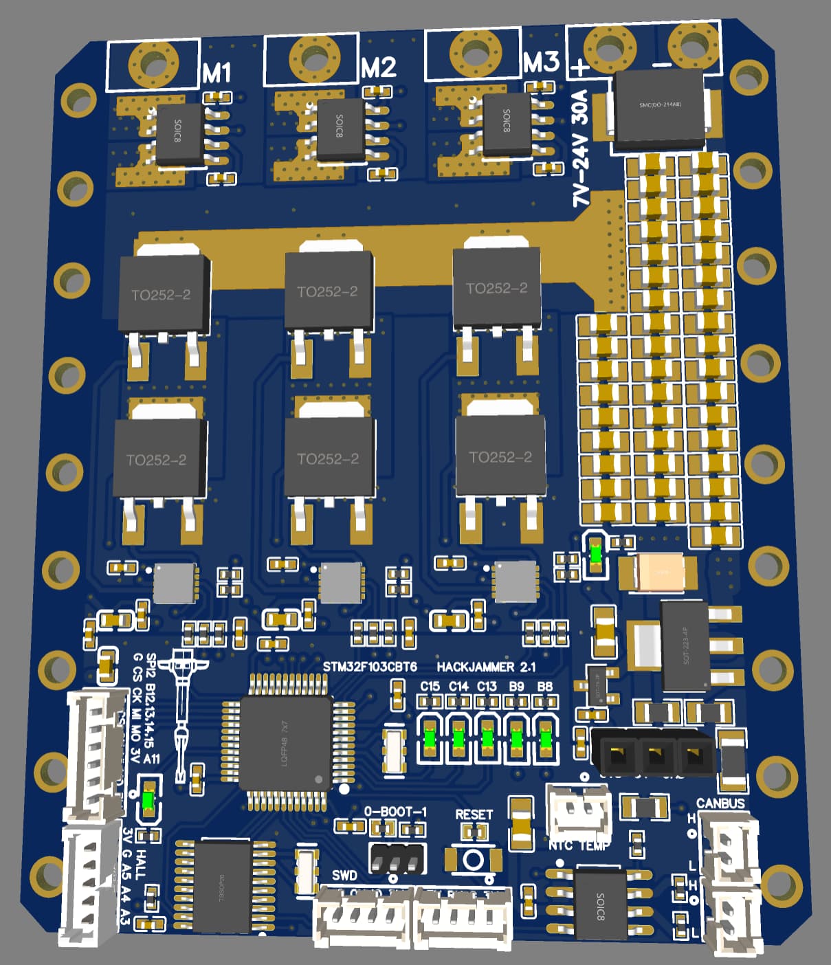
This is the link, solved the issues where the closed loop in angle control wont work, will post again when resolved. It was a fat finger that cost me two days and an embarrassment.
Put a lot of holes, so you can attach a heatsink.
Good luck with your project.
Please let me know how it goes.
Cheers,
Valentine
PS you will need an SWD debugger, you cannot use an USB directly like an Arduino. If you have a nucleo board, you can use the SWD pins to directly program the Hackjammer, but you need to solder yourself a bridge cable using the SWD mini pins. Ask me if you have questions.
PS2 I’ve excluded the pico-blade connectors from the BOM, because JLC will solder those manually, if you want them soldered by JLC you need to include them in the BOM. It costs extra.
---
### Author:  [@Valentine](https://community.simplefoc.com/u/Valentine)
#### Post date: [January 23, 2022, 1:42am UTC](https://community.simplefoc.com/t/experimental-high-current-driver-30a/1481/34 "2022-01-23T01:42:53Z")
> [@happytm](#):
>
> Interesting to get Hoverboard motors working
It’s just a motor. I picked it from the street, it was tossed in the trash.
---
### Author:  [@Valentine](https://community.simplefoc.com/u/Valentine)
#### Post date: [January 25, 2022, 11:57pm UTC](https://community.simplefoc.com/t/experimental-high-current-driver-30a/1481/35 "2022-01-25T23:57:00Z")
Servo motor, high torque, closed loop, 3D printed reduction gear.
Dynamic torque 70kg-cm
Stall torque 150kg-cm
Speed up to 500ms/rad
The arm you see is about 30cm, moving one pound soup can, at about 24v / 0.2A
Powered by the HackJammer 2.1 board, SimpleFOC closed loop angle with magnetic sensor.
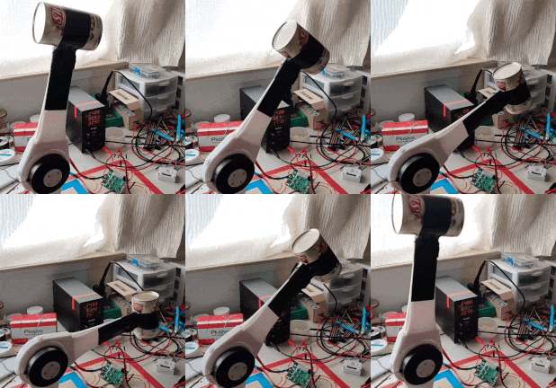
With a more powerful motor and better gears, that board could power a human sized arm to play arm wrestle with you, or box you to death.
My plans are to use a hoverboard motor, which is 100kg-cm, with reduction gear you could easily do 700kg-cm servo, which could lift 10kg off the floor or smack you so hard you regret you picked a fight with it.
The boards could be chained up using the integrated canbus to create a complex articulated arm to perform fine motions yet powerful enough to rival a human arm. All made cheaply in your bedroom, while waiting for damn pandemic to end.
# Citius, Altius, Fortius
PS if you haven’t noticed, how efficient FOC is, to achieve 70kg-cm dynamic torque with 200mA current @24V with 500ms/rad, it’s a bit hard to see from the crappy gif video.
---
### Author:  [@German\_io](https://community.simplefoc.com/u/German_io)
#### Post date: [January 27, 2022, 9:57pm UTC](https://community.simplefoc.com/t/experimental-high-current-driver-30a/1481/36 "2022-01-27T21:57:07Z")
Can you give more information about reducer ?
i parallel working on capstan based actuator 6:1 and 8108 motor. Im planing to use HackJammer for it to. Theoreticly this setup can give 7Nm dynamic torque 17Nm 40 rad\sec 24V.
And of course have perfect backdrive. But in my case it has 6 or 9 amp (vs you 0.2)
---
### Author:  [@Valentine](https://community.simplefoc.com/u/Valentine)
#### Post date: [January 27, 2022, 11:18pm UTC](https://community.simplefoc.com/t/experimental-high-current-driver-30a/1481/37 "2022-01-27T23:18:03Z")
The reducer is a very simple planetary gear 1:7, 3D printed, so whatever motor you attach, you get 7 times torque amplification.
The actual housing however is really complex 3D printed with integrated acetal bearings, you need really advanced 3D printer to print it, and a custom PCB board for the angle sensor. The entire reducer is 3D printed as a single part, and you need to get polymer acetal bearings, since I designed it with absolutely no metal inside, only polymer. Even my screws are nylon.
You could probably get faster angular speed, I haven’t tried, since my use case is power, not speed.
The mechanism is designed on SolidWorks 2020.
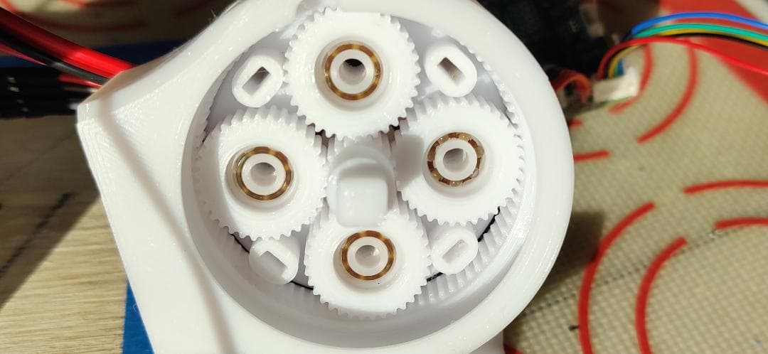
Actually, the inside tiny bearings are glass.
---
### Author:  [@Valentine](https://community.simplefoc.com/u/Valentine)
#### Post date: [January 27, 2022, 11:33pm UTC](https://community.simplefoc.com/t/experimental-high-current-driver-30a/1481/38 "2022-01-27T23:33:55Z")
> [@German\_io](#):
>
> in my case it has 6 or 9 amp (vs you 0.2)
The current actually also depends on the motor. I’m using a gimbal motor with high Ohm. If I use low ohm motor I’ll probably get high current too. You need high speed so gimbal will not work in your case. Also, polymer will tear up due to the dynamic load, you need steel reducer.
> [@German\_io](#):
>
> capstan based actuator
I like capstan actuators because you can combine them with bowden cableguides and move the motors outside. Problem is, this is extremely complex to design.
---
### Author:  [@Valentine](https://community.simplefoc.com/u/Valentine)
#### Post date: [February 3, 2022, 12:37am UTC](https://community.simplefoc.com/t/experimental-high-current-driver-30a/1481/39 "2022-02-03T00:37:30Z")
> [@Valentine](#):
>
> more powerful motor and better gears
My SoupHammer™ Servo driven by the HackJammer[R] board has been dramatically upgraded.
Behold the ultimate dual drive servo, capable of 14 N-m (theoretically estimated because it’s 3D printed of polymer and if I really get that much force the dynamic torque will chew up the plastic teeth inside).
The servo is driven by two symmetrical 100mm high-torque gimbals tied to the same axis.

Now I got to implement closed loop which is really tricky because I need to tie up a sensor on the outside.
Then I need a really big can of soup to test with.
All hail the SoupHammer™!!!
PS The HackJammer[R] is driving the two SoupHammer™ gimbals simultaneously with the same PWM but one is inverted. The other interesting point is that the resistance is halved (parallel coils). Also, this is at 12V. If you push 24V it could double the torque but will probably burn the coils.
---
### Author:  [@runger](https://community.simplefoc.com/u/runger)
#### Post date: [February 3, 2022, 11:18pm UTC](https://community.simplefoc.com/t/experimental-high-current-driver-30a/1481/40 "2022-02-03T23:18:59Z")
> [@Valentine](#):
>
> Now I got to implement closed loop which is really tricky because I need to tie up a sensor on the outside.
if I understand correctly the motors are mechanically tied together - will you control them as 2 motors, with 2 sensors, or is the intention to use only one sensor?
---
### Author:  [@Valentine](https://community.simplefoc.com/u/Valentine)
#### Post date: [February 3, 2022, 11:58pm UTC](https://community.simplefoc.com/t/experimental-high-current-driver-30a/1481/41 "2022-02-03T23:58:12Z")
> [@runger](#):
>
> mechanically tied together
They are hard coupled to a single axis and behave like one motor, and need one sensor, and twice the power (1/2 resistance). They must be exactly the same, and perfectly aligned else they will fight each other and the efficiency will drop. If I get metal gears and proper housing and cooling I could go to 20Nm, but that’s a fantasy. 14n-m is already twice the MIT Cheetah (continuous torque 6.9N-m)
[Previous page](https://community.simplefoc.com/t/experimental-high-current-driver-30a/1481.md?page=1)
[Next page](https://community.simplefoc.com/t/experimental-high-current-driver-30a/1481.md?page=3)