#include "drivers/drv8316/drv8316.h"
SPIClass SPI_1(SPI_MOSI, SPI_MISO, SPI_SCK);
BLDCMotor motor = BLDCMotor(11);
DRV8316Driver6PWM driver = DRV8316Driver6PWM(PHA_H, PHA_L, PHB_H, PHB_L, PHC_H, PHC_L, DRV_CS, true);
// velocity set point variable
float target_velocity = 20.0;
void setup() {
pinMode(LED_BUILTIN, OUTPUT);
digitalWrite(LED_BUILTIN, HIGH);
delay(100);
Serial.begin(250000);
Serial.println("Initializing...");
driver.voltage_power_supply = 12.0;
driver.voltage_limit = 12.0;
driver.init(&SPI_1);
driver.setSlew(Slew_25Vus);
driver.setPWM100Frequency(FREQ_40KHz);
driver.setBuckVoltage(VB_5V);
driver.setOCPRetryTime(Retry5ms);
//driver.enable();
Serial.println("Init complete...");
delay(100);
printDRV8316Status();
digitalWrite(LED_BUILTIN, LOW);
Serial.println("Done");
}
void loop() {
for (int i = 0; i < 6; i++) {
int pins[3] = { PHA_H, PHB_H, PHC_H };
for (int j = 0; j < 3; j++) {
if (i == j) {
for (int k = 0; k <= 40; k++) {
analogWrite(pins[j], k);
delay(10);
}
} else {
analogWrite(pins[j], 0);
}
}
}
}
```
Good news is the PCB is working well, no hardware errors found so far. I will look into the simplefoc code and check if anything is missed.
#### So far I have tested and confirmed these:
- MT6701 is working
- Driver SPI communication is good
- Driver Mosfets are working
So the only thing left to check is the simplefoc code. On the hardware side I still have to check the CAN transceiver.
PS: The lights you’re seeing in the video visualizes BLDC commutation. It is made with 6 leds in delta configuration along with diodes and resistors for protection.
---
### Author:  [@runger](https://community.simplefoc.com/u/runger)
#### Post date: [October 10, 2024, 3:07pm UTC](https://community.simplefoc.com/t/drv8316-stm32g431-design-request-for-comments/5421/27 "2024-10-10T15:07:38Z")
> [@rambros](#):
>
> I also checked the pwm outputs from the MCU. It is working well,
But you already mentioned that you could see the PWM output on the MCU? So that means SimpleFOC is working if that’s the case?
To me that would indicate there is still some kind of setup/initialization/enable problem that means SimpleFOC is producing output but the driver isn’t passing it on to the phases?
---
### Author:  [@runger](https://community.simplefoc.com/u/runger)
#### Post date: [October 10, 2024, 3:09pm UTC](https://community.simplefoc.com/t/drv8316-stm32g431-design-request-for-comments/5421/28 "2024-10-10T15:09:06Z")
PS: I love your commutation visualizer 🙂 would you mind sharing its design in the forum here? I think many people would like it!
---
### Author:  [@rambros](https://community.simplefoc.com/u/rambros)
#### Post date: [October 10, 2024, 4:34pm UTC](https://community.simplefoc.com/t/drv8316-stm32g431-design-request-for-comments/5421/29 "2024-10-10T16:34:39Z")
Yeah sure. Here’s the schematic.
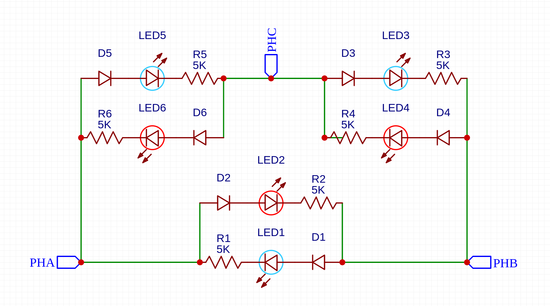
Step file and stls are available here: [GitHub - rambros3d/BLDC-LED-Visualizer](https://github.com/rambrosteam/BLDC-LED-Visualizer)
- Use diodes rated for your voltage. I use a maximum 12V, so this works fine.
- Use a different colour for odd leds ( LED1, LED3, LED5 ) and even leds ( LED2, LED4, LED6 ).
**The working principle is very simple:**
The diodes make sure the odd and even light up according to the current direction. For low voltages (below 5V) you can get away without diodes since LED are also diodes.
This setup is connected to a 3 phase driver output. It allows us to visualize the active phase and current direction.
---
### Author:  [@Candas1](https://community.simplefoc.com/u/Candas1)
#### Post date: [October 10, 2024, 4:57pm UTC](https://community.simplefoc.com/t/drv8316-stm32g431-design-request-for-comments/5421/30 "2024-10-10T16:57:05Z")
I once bought leds with 2 colors
> **[50pcs 5mm LED Bi-Color Clear Red/Green Non-Polar Round Light Emitting Diode...](https://www.aliexpress.com/item/32798281150.html?srcSns=sns_Copy&spreadType=socialShare&bizType=ProductDetail&social_params=60821936447&aff_fcid=e4dcbf478687431591527e10aec89b05-1728579426293-05097-_EzI0P2H&tt=MG&aff_fsk=_EzI0P2H&aff_platform=default&sk=_EzI0P2H&aff_trace_key=e4dcbf478687431591527e10aec89b05-1728579426293-05097-_EzI0P2H&shareId=60821936447&businessType=ProductDetail&platform=AE&terminal_id=fd5915a1beec477492d27aa3429371f5&afSmartRedirect=y)**
>
> Smarter Shopping, Better Living! Aliexpress.com
Could also work with Low voltage
---
### Author:  [@rambros](https://community.simplefoc.com/u/rambros)
#### Post date: [October 11, 2024, 7:05am UTC](https://community.simplefoc.com/t/drv8316-stm32g431-design-request-for-comments/5421/31 "2024-10-11T07:05:21Z")
# Finally got it working
## Platformio was the issue, Arduino IDE works
I am using the generic G431 config without cordic and fdcan enabled. I assume it is using the internal clock now. So I will create a board def next
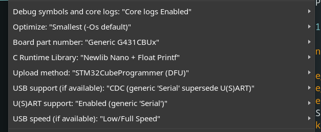
The past few days have been rough with this thing, Only last night I suspected that there might be some issue with platformio core since it is usually a bit outdated than the arduino cores.
Anyway It is finally working!
Look at that mesmerizing pwm.
* * *
> [@runger](#):
>
> > [@rambros](#):
> >
> > I also checked the pwm outputs from the MCU. It is working well,
>
> But you already mentioned that you could see the PWM output on the MCU? So that means SimpleFOC is working if that’s the case?
My bad friend, I was getting pwm from the MCU but all pins were giving the same voltage. That’s how suspected it might actually have to do something with the platformio core. Now with this Arduino core I can confirm that the pwm is actually changing voltage according to commutation.
I still have to do the following:
- create a board def for Arduino IDE
- test the closed loop modes
- test the CAN transceiver
@runger Huge thanks to you man
What a week fellas 👊
---
### Author:  [@runger](https://community.simplefoc.com/u/runger)
#### Post date: [October 11, 2024, 8:15am UTC](https://community.simplefoc.com/t/drv8316-stm32g431-design-request-for-comments/5421/32 "2024-10-11T08:15:16Z")
Hey, I’m really glad you got it working!
But I’m not sure its really an issue with platformIO - I use it all the time for my development on SimpleFOC, and the G431 is one of the more used chips I test with.
So its definitely possible to get it working with platformIO and a “generic” G431 board.
If you’re happy to use ArduinoIDE we can drop this topic, but if you’d like to make PlatformIO work we can compare versions and try to find the issue for you…
---
### Author:  [@rambros](https://community.simplefoc.com/u/rambros)
#### Post date: [October 11, 2024, 9:41am UTC](https://community.simplefoc.com/t/drv8316-stm32g431-design-request-for-comments/5421/33 "2024-10-11T09:41:08Z")
Yeah sure, I would like to find out what went wrong with the platformio setup. It would be nice to have both working.
I was just getting started with platformio, so I might have messed up something. This is my platform.ini file [https://github.com/rambrosteam/MicroSpora-SimpleFOC/blob/main/firmware/Driver-DRV8316\_diagnostics/platformio.ini](https://github.com/rambrosteam/MicroSpora-SimpleFOC/blob/main/firmware/Driver-DRV8316_diagnostics/platformio.ini)
* * *
I am also getting an error with [simplefoc arduino board defs](https://github.com/simplefoc/simplefoc_arduino_boards). I tried to compile a blink example for lepton board. same error with the new board also.
```auto
.arduino15/packages/STMicroelectronics/hardware/stm32/2.8.1/system/STM32G0xx/system_stm32g0xx.c:201:39: note: in expansion of macro 'VECT_TAB_OFFSET'
201 | SCB->VTOR = VECT_TAB_BASE_ADDRESS | VECT_TAB_OFFSET;
```

I have also added this board to the fork (still need to configure clock settings), I will create a pull request once its ready.
> **[GitHub - rambros3d/simplefoc\_arduino\_boards: Arduino board vendor files for SimpleFOC boards](https://github.com/rambros3d/simplefoc_arduino_boards)**
>
> Arduino board vendor files for SimpleFOC boards
---
### Author:  [@rambros](https://community.simplefoc.com/u/rambros)
#### Post date: [October 11, 2024, 10:36am UTC](https://community.simplefoc.com/t/drv8316-stm32g431-design-request-for-comments/5421/34 "2024-10-11T10:36:15Z")
> [@rambros](#):
>
> I had this in the _platform.ini_ build flags. But don’t know why it doesn’t work.
>
> 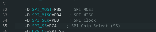
Now I know whats wrong, I left out the **PIN\_** prefix
It is supposed to be like this:
```auto
-D PIN_SPI_MOSI=PB5 ; SPI MOSI
-D PIN_SPI_MISO=PB4 ; SPI MISO
-D PIN_SPI_SCK=PB3 ; SPI Clock
-D PIN_SPI_SS=PC4 ; SPI Chip Select (SS)
-D DRV_CS=PIN_SPI_SS
```
With this I can now use the default SPI. No need to manually define a new SPI class.
---
### Author:  [@rambros](https://community.simplefoc.com/u/rambros)
#### Post date: [October 16, 2024, 11:58am UTC](https://community.simplefoc.com/t/drv8316-stm32g431-design-request-for-comments/5421/35 "2024-10-16T11:58:09Z")

```auto
.arduino15/packages/STMicroelectronics/hardware/stm32/2.8.1/system/STM32G4xx/system_stm32g4xx.c: In function 'SystemInit':
: error: expected expression before '{' token
.arduino15/packages/STMicroelectronics/hardware/stm32/2.8.1/system/STM32G4xx/system_stm32g4xx.c:199:39: note: in expansion of macro 'VECT_TAB_OFFSET'
199 | SCB->VTOR = VECT_TAB_BASE_ADDRESS | VECT_TAB_OFFSET;
```
I can’t get the [arduino\_simplefoc\_boards](https://github.com/simplefoc/simplefoc_arduino_boards) working. This error shows with both boards, lepton and microspora.
The generic board defs compile well, but not the simplefoc defs
@runger can you please give some advice, I’m totally lost here.
---
### Author:  [@runger](https://community.simplefoc.com/u/runger)
#### Post date: [October 16, 2024, 12:17pm UTC](https://community.simplefoc.com/t/drv8316-stm32g431-design-request-for-comments/5421/36 "2024-10-16T12:17:14Z")
I will look into this later this week, and try to add your board and the quadrans also… I’m a bit busy today…
---
### Author:  [@rambros](https://community.simplefoc.com/u/rambros)
#### Post date: [October 16, 2024, 1:05pm UTC](https://community.simplefoc.com/t/drv8316-stm32g431-design-request-for-comments/5421/37 "2024-10-16T13:05:27Z")
Thanks a ton man. I don’t think I could have got this working without your help 🤝
---
### Author:  [@rambros](https://community.simplefoc.com/u/rambros)
#### Post date: [October 16, 2024, 2:20pm UTC](https://community.simplefoc.com/t/drv8316-stm32g431-design-request-for-comments/5421/38 "2024-10-16T14:20:39Z")
#### Position mode example
* * *
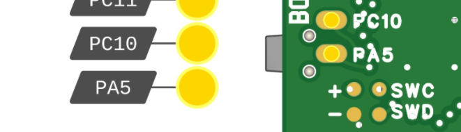
Found a minor error:
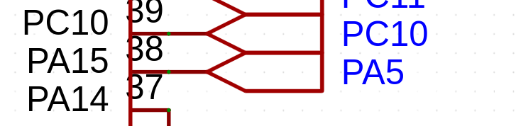
I mislabelled PA15 as PA5. It is an exposed gpio at the bottom of the PCB.
That will be corrected in V2.
### Some more photos of the board
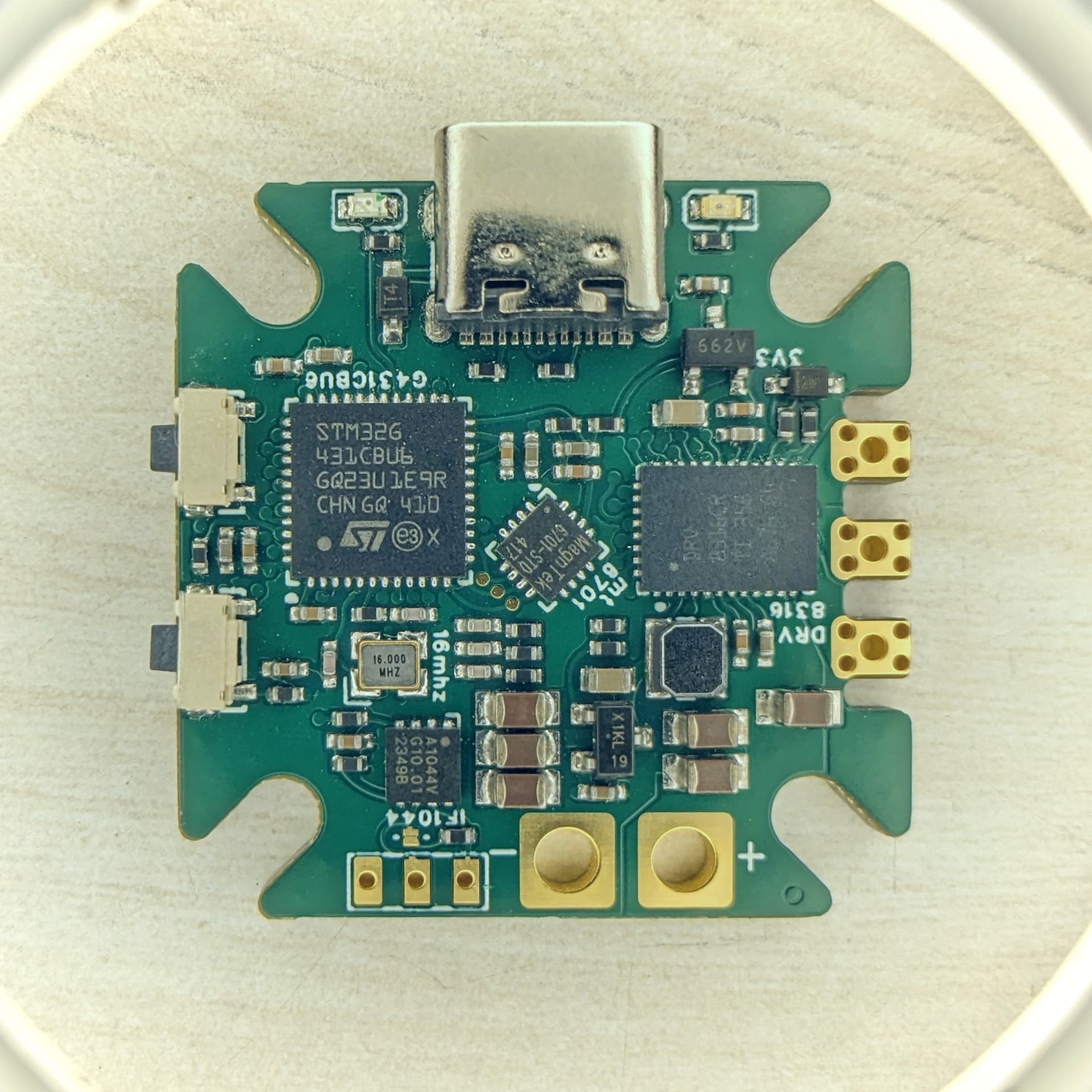
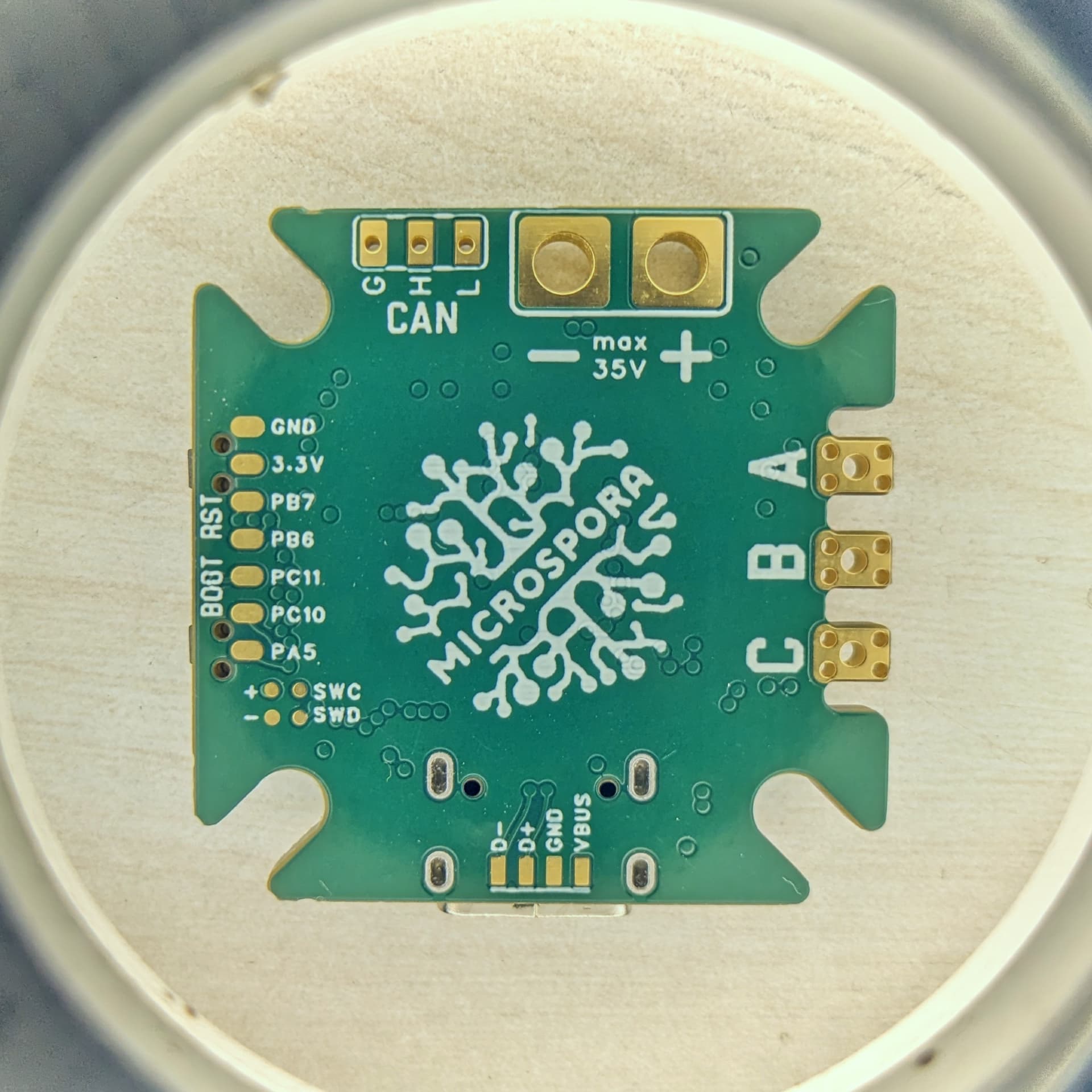
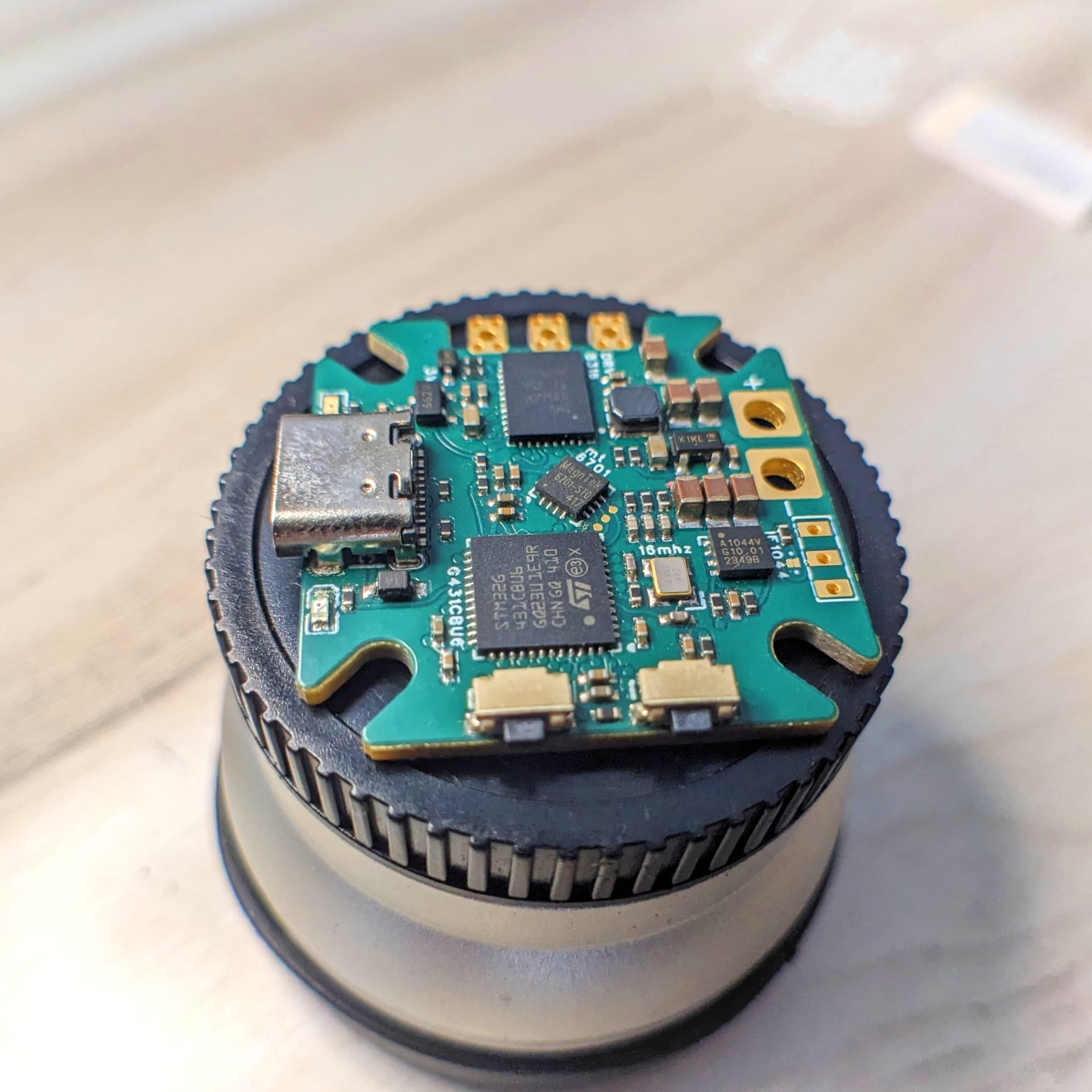
---
### Author:  [@Daan87423](https://community.simplefoc.com/u/Daan87423)
#### Post date: [October 20, 2024, 8:39am UTC](https://community.simplefoc.com/t/drv8316-stm32g431-design-request-for-comments/5421/39 "2024-10-20T08:39:19Z")
I’m currently testing a similar setup with the DRV8316EVM and an STM32G431 Nucleo. Have you been able to get the low-side current sense to work?
Closed-loop torque control using voltage works, and currently trying to monitor the d and q currents using step 4 from the [getting started](https://docs.simplefoc.com/example_from_scratch#step-4-testing-the-current-sense---if-available). But getting an nFAULT (not sure which one) on the EVM and serial monitor gets stuck at:
STM32-DRV: Syncronising timers! Timer no. 1
STM32-DRV: Restarting �
I’ll try switching the default SPI DRV8316 to the non-SPI DRV8316C and see if it has anything to do with the DRV8316Driver6PWM.
```auto
#include "Arduino.h"
#include
#include
#include
#include "drivers/drv8316/drv8316.h"
BLDCMotor motor = BLDCMotor(1);
DRV8316Driver6PWM driver = DRV8316Driver6PWM(PA8,PB13,PA9,PB14,PA10,PB15,PB6,false,PB10,PB12); // use the right pins for your setup!
// hall sensor instance
HallSensor sensor = HallSensor(PB4, PC11, PC10, 1);
// channel A and B callbacks
void doA(){sensor.handleA();}
void doB(){sensor.handleB();}
void doC(){sensor.handleC();}
//current sense
LowsideCurrentSense current_sense = LowsideCurrentSense(2700, PA2, PA1, PA0);
//target variable
float target_voltage = 2;
// instantiate the commander
Commander command = Commander(Serial);
void doTarget(char* cmd) { command.scalar(&target_voltage, cmd); }
void printDRV8316Status() {
DRV8316Status status = driver.getStatus();
Serial.println("DRV8316 Status:");
Serial.print("Fault: ");
Serial.println(status.isFault());
Serial.print("Buck Error: ");
Serial.print(status.isBuckError());
Serial.print(" Undervoltage: ");
Serial.print(status.isBuckUnderVoltage());
Serial.print(" OverCurrent: ");
Serial.println(status.isBuckOverCurrent());
Serial.print("Charge Pump UnderVoltage: ");
Serial.println(status.isChargePumpUnderVoltage());
Serial.print("OTP Error: ");
Serial.println(status.isOneTimeProgrammingError());
Serial.print("OverCurrent: ");
Serial.print(status.isOverCurrent());
Serial.print(" Ah: ");
Serial.print(status.isOverCurrent_Ah());
Serial.print(" Al: ");
Serial.print(status.isOverCurrent_Al());
Serial.print(" Bh: ");
Serial.print(status.isOverCurrent_Bh());
Serial.print(" Bl: ");
Serial.print(status.isOverCurrent_Bl());
Serial.print(" Ch: ");
Serial.print(status.isOverCurrent_Ch());
Serial.print(" Cl: ");
Serial.println(status.isOverCurrent_Cl());
Serial.print("OverTemperature: ");
Serial.print(status.isOverTemperature());
Serial.print(" Shutdown: ");
Serial.print(status.isOverTemperatureShutdown());
Serial.print(" Warning: ");
Serial.println(status.isOverTemperatureWarning());
Serial.print("OverVoltage: ");
Serial.println(status.isOverVoltage());
Serial.print("PowerOnReset: ");
Serial.println(status.isPowerOnReset());
Serial.print("SPI Error: ");
Serial.print(status.isSPIError());
Serial.print(" Address: ");
Serial.print(status.isSPIAddressError());
Serial.print(" Clock: ");
Serial.print(status.isSPIClockFramingError());
Serial.print(" Parity: ");
Serial.println(status.isSPIParityError());
if (status.isFault())
driver.clearFault();
delayMicroseconds(1); // ensure 400ns delay
DRV8316_PWMMode val = driver.getPWMMode();
Serial.print("PWM Mode: ");
Serial.println(val);
delayMicroseconds(1); // ensure 400ns delay
bool lock = driver.isRegistersLocked();
Serial.print("Lock: ");
Serial.println(lock);
}
void setup() {
Serial.begin(115200);
SimpleFOCDebug::enable(&Serial);
sensor.pullup = Pullup::USE_EXTERN;
sensor.init();
sensor.enableInterrupts(doA, doB, doC);
motor.linkSensor(&sensor);
driver.voltage_power_supply = 24;
driver.init();
motor.linkDriver(&driver);
current_sense.linkDriver(&driver);
// current sense init hardware
if(!current_sense.init()){
Serial.println("Current sense init failed!");
return;
}
// link the current sense to the motor
motor.linkCurrentSense(¤t_sense);
motor.voltage_sensor_align = 6;
// set motion control loop to be used
motor.torque_controller = TorqueControlType::voltage;
motor.controller = MotionControlType::torque;
motor.useMonitoring(Serial);
motor.monitor_downsample = 100; // set downsampling can be even more > 100
motor.monitor_variables = _MON_CURR_Q | _MON_CURR_D; // set monitoring of d and q currents
// initialize motor
if(!motor.init()){
Serial.println("Motor init failed!");
return;
}
//motor.zero_electric_angle = 0;
//motor.sensor_direction = CW;
// align sensor and start FOC
if(!motor.initFOC()){
Serial.println("FOC init failed!");
return;
}
Serial.println("Init complete...");
command.add('T', doTarget, "target voltage");
delay(100);
printDRV8316Status();
}
void loop() {
// main FOC algorithm function
motor.loopFOC();
// Motion control function
motor.move(target_voltage);
// display the currents
motor.monitor();
// user communication
command.run();
}
```
---
### Author:  [@rambros](https://community.simplefoc.com/u/rambros)
#### Post date: [October 22, 2024, 8:51am UTC](https://community.simplefoc.com/t/drv8316-stm32g431-design-request-for-comments/5421/40 "2024-10-22T08:51:47Z")
I also didn’t get the current sense to work, I got the error that current sense was not initialized, but not the timer error. I tried different gain settings in 8316.
Currently I am occupied with another project.
I will look into it again next week. I am determined to get this fully working.
* * *
edit: here’s the code I tried
Torque control [MicroSpora-SimpleFOC/firmware/MicroSpora-FOC\_Control/SimpleFOC\_Torque/SimpleFOC\_Torque.ino at main · rambros3d/MicroSpora-SimpleFOC · GitHub](https://github.com/rambros3d/MicroSpora-SimpleFOC/blob/main/firmware/MicroSpora-FOC_Control/SimpleFOC_Torque/SimpleFOC_Torque.ino)
ADC test - [MicroSpora-SimpleFOC/firmware/MicroSpora-Test\_Utils/Current\_sensor-adc\_test/Current\_sensor-adc\_test.ino at main · rambros3d/MicroSpora-SimpleFOC · GitHub](https://github.com/rambros3d/MicroSpora-SimpleFOC/blob/main/firmware/MicroSpora-Test_Utils/Current_sensor-adc_test/Current_sensor-adc_test.ino)
Even the adc test was problematic, I absolutely have no idea what’s up with stm32 and drv8316.
[Previous page](https://community.simplefoc.com/t/drv8316-stm32g431-design-request-for-comments/5421.md?page=1)
[Next page](https://community.simplefoc.com/t/drv8316-stm32g431-design-request-for-comments/5421.md?page=3)