First of all, a huge thanks to the developers for all your efforts, I know you are investing an enormous amount of time into this project and I am a huge fan. I wanted to use SimpleFOC for my research project, but eventually I had to abandon it due to some flaws. I would love to work on them myself, but unfortunately, I am extremely busy in the last months of my PhD (I hope to contribute after that). Nevertheless, by writing down my observations, I hope to still be able to make a small contribution right now:
A lot of people seem to struggle with current control because of various reasons (see below). This is fine, current control is hard. However, I often read in this forum to use a low-pass filter if the current readings are not good and to adjust it as slow as tau= 0.01s. I don’t think this is good practice, because with this, the current controller will never be able to regulate the current in a satisfactory way as typical motor time constants are around tau_motor = 0.0002, …, 0.001. By using those very slow filters, we create slower systems that appear to be better controllable, but in reality we just hide the fast motor winding dynamics.
At the same time, the gains for the current controller seem to be recommended to be chosen rather arbitrarily and in general very low. Instead, we should start to rely on control theory. For example, in case no current low-pass filter is used, there is a very elegant way of cancelling a pole in the open-loop system, by setting K_i = K_p*R/L (because SimpleFOC uses a parallel PI) and choosing K_p with K_p = L *omega, where omega is the desired bandwidth. See for example here: Teaching Your PI Controller to Behave (Part III) - Industrial - Technical articles - TI E2E support forums. A typical value for omega is around 1500 rad/s, which is in the same range as the intrinsic motor winding dynamics and which should usually be feasible with a current control sampling frequency of ca. 20kHz and reasonable noise. Of course, a similar procedure could be done in discrete time or with an additional filter.
This brings me to the next point. Unfortunately, I didn’t have enough time to check everything, but it seems like (at least with the B-G431B-ESC1) we have an issue with the current measurements as they are very noisy. I eventually ended up using the ST Motor Control Firmware and it gave me much better current readings which a noise that was very acceptable for the motor I used. This confirms that it’s not a hardware issue. Maybe, we (I will help as soon as time allows) should double check again the alignment, timing and settings of the ADC for the current readings. It seems to me like the noisy measurements are kind of a deal-breaker for SimpleFOC, which is very sad.
At the same time, maybe we need to rethink the architecture and the fact that the current controllers are independent of the current measurement. It is usually beneficial to have the current controller updates aligned with the current readings (see for example the code for the TI or ST motor control dev boards). Current control is really sensitive and we want to make sure to guarantee regular, timely and quick (>= 20kHz) updates. Maybe reconsider using interrupts coupled to the ADC readings?
To conclude, it would be amazing if we could figure out the remaining issues with the current readings and I think the SimpleFOC project would highly benefit from a more theoretical approach to control instead of trial and error. I am very curious to get any opinions of other users or developers on this topic.
If the ST firmware uses the CORDIC, then it is a hardware advantage?
Low side current sensing requires perfect timing, whereas inline sensing is more forgiving. Just wanted to mention that the board you are mentioning is using low_side current sensing. Tell me, what are the general advantages to low side sensing compared to inline?
Thanks for your reply. Fair point, the ST firmware employs the CORDIC to compute the square root and trigonometric functions. But I am also not asking SimpleFOC to run at 50kHz, so I am not sure how this relates to my post above.
Yes, I see that the board uses low side current sensing. So the ADCs have to be carefully aligned with the PWMs (which might or might not be the case, I didn’t have time to check, but I rather suspect it not to be the case). Well from what I understand, low side sensing has benefits in terms of circuit design as the opamps are closer to ground. Anyway, I don’t think we need to discuss this, I didn’t design the hardware
Edit: Btw, why does SimpleFOC actually support both, inline and low-side for this specific board (according to the doc) if the hardware is built for low-side?
Welcome to the forum, and thank you for contributing. Your input is interesting and valuable.
Have you really tried to use the SimpleFOC with an MCU board, driver and motor, and systemically and experimentally confirmed and measured and proved your observations with different hardware and setups for various use cases, as well as read the actual code and understood the hardware internals, or these are just off-the-cuff comments you are making? Could you please back your comments and input with hard measurements, test use cases, and post your experimental results? That would help us constructively assess your inputs.
@Valentine
Thanks for your reply. No, I have to admit that I didn’t spend time doing systematic measurements comparing inline and low-side current sensing and I also didn’t compare the values with a current probe (only multimeter to roughly verify the gains), nor did I record the current measurements.
I spent 2-3 days with the B-G431-ESC1 board and a Faulhaber BLDC motor with AMC Cui encodeder, and when I realized that my current measurements were very noisy (correct values, but too noisy) even though I followed the examples and instructions, I switched to the ST firmware, because we needed it for work and we needed something asap.
I am sure that I can make the B-G431 work somehow with enough time (I don’t exclude that I made some mistake somewhere), but I guess I also just wanted to raise awareness that we should always first check the theoretical part (which bandwidths do we want to achieve, etc…) before going for trial and error.
As I said, my free time is currently basically non-existing, but I will try do some recordings in the next few days and I will post them. Would be great to have a 1:1 comparison with the ST firmware actually.
I am happy to hear some proper control theory questions and remarques, I think that we dont have them enough.
This is true. The low pass filter is really not intended for smoothing the torque control dynamics (or making it more stable) but to filter the current values. And it is absolutely true that having the time constant around 0.1 is far to big and even strange to be working at all. (BTW the same is true for the velocity Low pass filter).
However, the low pass filters in the simplefoc are placed on the D and Q current not on phase currents so even though they are very crucial for the good dynamics they will not ruin the vector alignment. That is probably why such values even work.
In my opinion, whenever such solutions are necessary it means either one of the two things (which you also very nicely pointed out):
PI gains are off and they need to be re-tuned ( lowered in most cases )
Current sensing is very noisy
Yeah recommending the gains is very tricky and as many of our users are using gimbal motors with higher phase resistance and lower currents many of our examples are using relatively high current control gains. And you are definitely right that we need a better way for tuning the current loops. For now we support the SimpleFOCStudio which can be used to find good parameters but its still hand tuning and requires at least a good idea of initial values.
I would really really like to automate the current control loop and I’ve been looking into some papers to determine the best ways and I hope to be able to do so soon. And I’m definitely open to any type of collaboration on this subject.
However, an important thing to say is that we are searching to find a general solution to these problems, not a solution which works on one board/driver/motor/etc. So this adds a lot of complexity to the problem definition and the way it needs to be implemented.
It is very likely that we will never be able to reach the performance of the STM or Microchip firmware for BLDC motors simply because we are choosing not to make our code so hardware specific.
The code for the BG431B board is actually a contributed code from our community
and the current sensing is very specific to this board. I personally do not even own one and did not test it at all.
The PWM/ADC alignment is done using injected channels and the code uses the integrated opamps in the STMG4 chip. There is probably room for improvement in terms of performance and we’d be happy to collaborate over this.
All of our stm32 based low-side sensing is based on the ADC injected channels and TRGO events that are triggering the ADC conversion exactly in the middle of the time the low-side mosfets are active (which is effectively the start of the center aligned duty cycle). This is not the most optimal synchronization technique, I think that the STM motor suite uses the fourth timer channel to trigger the ADC which will usually result in a bit more precise measurements. But at this point we decided not to use this option because we do not want to use additional timer channel for the ADC sync as the user might prefer to use it for something else. But this might change in future.
So at the moment, to avoid potential problematic situations due to the ADC conversion lasting to long and entering the high-side activation of certain mosfets we suggest using the PWM frequencies that do not exceed 20kHz. This in most cases results in behavior.
However there are many things that can be done to improve the low-side and inline current sensing implementation that we have currently. They are really in their early stage of developement.
This would once again be very very hardware specific. It is doable of course but at the moment the choices that we’re taking are oriented towards the cross-platform implementations more than to the optimal performance.
On the separate note, SimpleFOC loop times in the low-side current sensing mode are sometimes faster than the PWM frequency and the ADC conversion which means that effectively you get more than one update of the current target per PWM duty cycle. So we might be able to achieve the behavior you’re describing even without the interrupts.
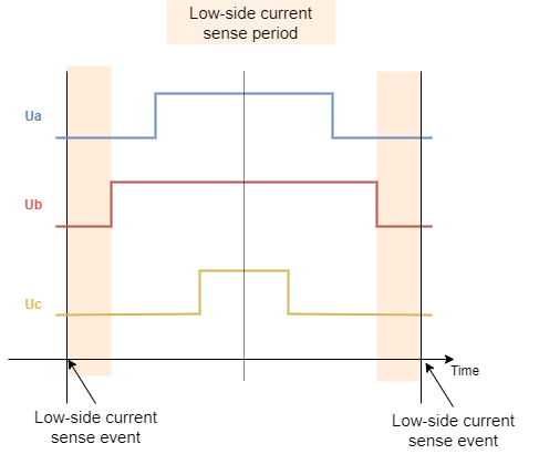
The PWM and the ADC conversion is aligned for the low-side current sensing at the center of the low-side active interval. Here is the diagram.
As I said already starting the conversion at the center is not the best place to start the ADC conversion, it would be better to start it a bit before to be measuring the currents at the center of the all phases low part of the duty cycle. But as long as the timing is consistent and the PWM frequency is not too high the current measurements should be good.
Finally the current control in the simplefoc is at its early stage and I am not really happy with the results yet, I hope we will be able to improve its performance in the future. And we are open to any type of collaboration
Current control is complicated and requires some experience and having more control engineers onboard would be great!
We don’t actually. We only support the low-side current sensing for this board. This is a legacy issue because when the guys implemented the low-side current sensing on this board the library did not have lowsidecurrent sense interface so they used the inlinecurrentsense class. Later we’ve added the low-side current sense interface to the simplefoc and for this board we kept both implementations. So using inline or low-side current sensing interfaces will both use the same low-side code.
I’m starting to understand the H7 fascination. 16bit fast ADC is just miles from 12bit “normal” ADC.
Then I see the 0.8mm pitch (14x14mm) BGA footprint. Looks less scary compared to 0.5mm pitch (7x7mm) wafer ball’s, maybe it’s just a mental thing. Has anyone tried to rub solderpaste into the footprint with soldermask recess. I mean without a stencil but just fill those soldermask cavities and then place the part?
I’ve tried to fill the laser cut mask manually. It works and I got decent results. But it’s such an annoying task I’d have to be really desperate to do it. You need a syringe and magnifying goggles or a microscope. And the patience of a raccoon trying to open a trashcan full of delicious garbage.
Yeah we all need patience at this moment in space and time. If it works it works. If it is possible, then applying paste with a small spatula, for prototypes, doesn’t seam unrealistic. It’s those darn via in pad’s, who takes it to another level.
Thank you so much for your response and the insight into the development of SimpleFOC. It’s great to learn about all the thoughts you guys put into this project! I see, there are still many things to learn about the codebase and the community. As mentioned earlier, I will do my best to report some measurements to address the issues that I am having specifically with the B-G431. But as soon as I have more time, I will also be very happy to dive deeper into the code base and to eventually even contribute to this project.
The 14x14mm footprint allows microvias in between ball´s. No wonder why Arduino used that format.
So, the MCU industry is at a critical juncture, or punkture. This is capitalism @its_finest. Big wallet keeps the opensource community from progress, by effectively short circuiting the supply chain.
Which brings os to our next proposition; watch some more fiction to escape this sad reality, where war machines are being produced @the_expence of actually useful tech… Long live the borders of sovereign states, the confines of our souls.
Don’t hesitate to contact me or the team directly in if you need some support for starting with the simplefoc!
This is the case for anyone that wants to contribute, don’t hesitate to seek assistance from us, we’ll be happy to guide/support you in any way we can
Just want to inform the forum; Portenta H7 is in stock and this is in my opinion a good way to develop on the STM32H747. When I wrote above ranting about shortage, I did not know the Portenta H7 “lite” can be purchased.
The standalone MCU is in shortage like so many other, but that should IMO not discourage anyone from going into the development. And yes those H7 MCUs also have the CORDIC.
Sorry to revive this thread, but as I was studying the STM current sensing a bit in the past, I know what they do differently that is missing in SimpleFOC that might help reduce the noise.
adc calibration, I tried it on STM32F1 only. This is easy to add and helping with the accuracy
with low side sensing and 3 shunts, use only the 2 phase currents of the phases with lowest duty cycle for the foc calculation (STM is even reconfiguring the adc to only sample those 2 phases, but it’s more complicated and very hardware specific). This only helps at high duty cycles. @VIPQualityPost said he would be interested in implementing this.
changing the sampling point. They have complicated rules to move the sampling point avoiding sampling while one of the phase is turning ON.
Hmm… I was under the impression that because the PWM was center-aligned, that the trigger for reading ADC would be in the center of pulse → not during state transitions. Is that not the case?
Yes
I don’t know if we need to do this. I don’t know output impedance of common current sense amplifiers but it’s also possible to reduce the sampling time by providing a lower-impedance source, to charge the sampling capacitors more quickly. The sample time cannot also be too long or there is leakage error as well.
We measure the current in the middle but the rise time + noise time might impact after the middle.
So even if you don’t want to use the phase current A because the ON time is not high enough, the switching of this phase might add noise to the other phase current sample.
The picture I have shared shows it:
Good point. Maybe with an additional opamp you can do a differential measurement between phases, and then null this noise but I think that sounds like maybe too much work. Depending on the length of transition the sampling time may average out this noise anyway.
This seems to be the only case when they sample before the middle, and it’s at high duty cycle.
So if people report noise with current sensing at low duty cycle, there is another problem.
If it’s at high duty cycle, using only 2 phase currents should probably already help.
On my current hardware, I have only 2 shunts, so I cheat a bit by sampling after the middle to compensate for the delay. So I can go fractions of duty cycle higher.
I was not aware the filter time constant was so large, I have used current sensing on this board but not the current control. I agree it’s a common phenomena, we are all tempted to simply filter out glithes etc but it makes the system too sluggish at some point. Encountered this many times in the last year or so.
With your second point, I only understand the basics of pid controllers and I’m afraid I would have to read that doc and still might not understand, but I will put it on my reading list. The approach of just making the gains real low and letting the user adjust them is a good first step, maybe your suggestions are the next, although I would be wary of complicating things. If it’s some kind of auto-tune like module that would make sense, otherwise I would just write a document that tells users how to set the gains to a reasonable range. That seems super easy and fast, just writing good documentation is an intermediate thing I am a big fan of, it’s really easy and fast compared to making a good technical system but it’s sure a lot better than nothing.
I also noticed the current measruements are quite noisy and I think they may be too noisy for sensorless motor control of most kinds, however I think that we need to focus on a better board before spending a lot of time improving the software for this board, for many reasons. It is not a great design in many ways and also the boards are not licensed for use in actual products, and they really aren’t general purpose, and the supply of them is also not reliable, so much of the work that goes into improving the software could be lost.
I have heard that inline sensing is generally superior to low side sensing except slightly more expensive. And this MCU only has 3 ADC inputs and 3 op amps (or is it 2 op amps? that would suck) which I think is enough? With low side, which this board uses, it measures the current going into (out of?) the triple half-h-bridge, not at the actual terminals of the inverter, (the outputs of the half-h-bridges) so you have to synchronize with the PWM signal to ascertain which leg the current is actually flowing into and out of etc. but that seems like it could lead to noise in various ways. I am a fan of addressing noise and other error sources as low down as possible, to do otherwise tends to have side effects and complicate things downstream. As an aside, it may be possible to improve the noise by changing the way the sample is taken but IDK.
Are you sure the ST motor control firmware isn’t just using some extra filtering to make things look smoother? I know they have a sensorless FOC example code, which requires good current readings, and it’s supposed to be open source but it’s some kind of machine generated code that with my limited knowledge I couldn’t make any sense of.
I think because the low side current approach is used here we cannot have >20 khz current measurement.
I too am a big fan of an approach that is drawn from the fundamentals, and have seen this succeed remarkably well in many cases. The reason it is not taken is that the people that have the expertise are hard to find and the rest of us want to get on with things, so we just take something and rumble, and to be fair that gets the ball rolling. With open source we can leverage the knowledge of the different players and slowly accrue a truly elegant system that is very powerful and enduring, as has been seen several times now in the open source and even closed source industries. I know for instance some CAM programming software by autodesk is actually largely based on some academic research on the process (direct from STL rather than parametric curves) and it really does work a lot better in many ways. LinuxCNC also has many advantages although it could use more labor hours there is a solid foundation that I respect a lot, and I think simpleFOC can evolve to this point relatively quickly.