B-G431B-ESC1: Beginner guide + I2C guide

Hi @Edgar_Pisano,

No problem! Great work! I also hope it works on Arduino IDE! :slight_smile:

ROS is still on my bucket list. I am hoping to follow some courses in it next year. ROSSerial can be a possibility. If I would implement ROS some day in the far future for my robot, I was planning to use CAN communication with an Rasberry Pi and a CAN module. I do not know exactly what your plan is with the board and ROS but maybe it could also be a possibility were you can look into!

My B-G431B-ESC1 seems to be working great with the Arduino IDE following these steps :slightly_smiling_face:. I managed to get the AS5048A magnetic sensor working in PWM mode as well (connected to the HALL1 pin) by creating a new sensor type heavily based on the existing MagneticSensorAnalog .cpp and .h files. I am getting some oscillations in closed loop velocity/position control modes at low speeds, but I imagine that is mostly due to lack of proper tuning and a relatively high kv motor (650kv).

Thanks for the guide!

1 Like

Nice work @JordanCormack - Perhaps youā€™d like to submit your MagneticSensorPWM sensor as a pull request so that others can use it?

You might want to play with the motor.LPF_velocity.Tf e.g increasing it a little e.g. from 0.005 to 0.05. Ideally you want to keep Tf low but If you are mostly constant speed you can increase it a fair bit.

Great work @JordanCormack! Nice to see that many people are experimentating with FOC and this board :slight_smile:. What kind of max speeds are you getting with this sensors? My speed is max around 60 rad/s what is not the desired speed I want so I was looking to get full FOC - current mode working.

I was curious if there are people who already managed to get FOC - current mode working on this device?

I am already stuck at getting the current sensors working. Looking at the datasheet it is using 0.003 ohm shunt resistors. Only the amplification gain is a bit more difficult because is using the internal op amps of the chip itself.

These internal op amps can be enabled with a HAL module. Only problem is that is not a simple HAL module that can be turned on or off like I2C. This HAL module needs first to be configured before it can be enabled. I am currently looking into how to configure such a file so that it can be used with STM32duino. I think that stm32cube can be useful for this.

Are there any people who already manage to do this? Or have experience how to configure these kind of files and have any tips for me?

@Owen_Williams I will try adjusting the motor.LPF_velocity.Tf later and see if that helps. Once I have done some more tuning and I am sure my oscillation issues are not related to the sensor I will submit a pull request.

@Wittecactus I havenā€™t had it running anywhere close to 60 rad/s yet, or tried any FOC current mode, but I will report back if I do!

1 Like

Hey @Wittecactus,
There is a thread initiated by @scouttman few weeks ago.
He managed to do it with the v2.0.2 :smiley:

1 Like

You are missing a step. A virgin Arduino install will also need to explicitly go to Boards Manager, and search for stm32, and install the STM32 Package first. Until this, the directories you describe below do not exist and you will be missing the whole thing you want to replace.

Other than that, the board worked, using the Arduino IDE, the install is pretty quick. Thank you for compiling the guide.

1 Like

For those of you interested in the driver, an update. Got some time over the weekend, here is the result.

Setup:
Software:
Windows Server 2019 Host.
VMWare Workstation Pro 16
Windows Server 2019 Guest.
USB Pass-trough from host to guest
Arduino clean install on guest
Simple FOC clean git pull
Wittecactus instructions for board deployment on Arduino

Hardware:
B-G431B-ESC1 Board
12 V Power Source
100 MHz Oscilloscope

Connect and turn blue potentiometer on DB. This is the expected result. You will see the control wave between any of the three pole wires on the oscilloscope. With the potentiometer, you control the speed of the motor. Oscilloscope waveform will change.

You must modify the sample code below to scale the speed else gruesome injuries may occur if you decide to connect a live motor! Also must fix motor to solid testbed unless you want to decapitate yourself.

The board reverse voltage protection works fine, I connected for 30sec reverse polarity to test, it just got really hot and nearly de-soldered. The Transil on the board prevents damage in case of reverse polarity at the input side for a low time. Not sure how low is low time, but it drew 4 Amps and in 30 sec noticeably overheated. YMMV. If you have good liquid cooling it may survive for a while.

The board is a dev board. The layout is rather poor. The board is dense and really hard to solder, I needed a microscope. If you need high current you will need copper solder boots and liquid cooling. I mean dunk it in dielectric coolant (fluorinert, novec, etc). Even idle the board draws 0.1A which will overheat it really fast. Whoever designed the board didnā€™t allow for proper heat-sinks and screw boots, only solder. But for $18, I canā€™t complain, this is a terrific deal.

Apologies for the literal test bed on the pic, covid forced me to work from home and I canā€™t get to my nice lab at work.

If I have time I will post the coolant solution.

Iā€™ll try to check the others solutions I saw someone did a current control, will try.

Itā€™s a great board and a great price point.

Sample absolute minimal code for velocity control via daughter-board potentiometer:

#include <SimpleFOC.h>

// NUMBER OF POLE PAIRS, NOT POLES
BLDCMotor motor = BLDCMotor(7); 
// MUST USE 6PWM FOR B-G431 DRIVER
BLDCDriver6PWM driver = BLDCDriver6PWM(PHASE_UH, PHASE_UL, PHASE_VH, PHASE_VL, PHASE_WH, PHASE_WL); 

void setup() {

  // driver config
  // power supply voltage [V]
  driver.voltage_power_supply = 12;
  driver.init();

  // link the motor and the driver
  motor.linkDriver(&driver);

  // limiting motor movements
  motor.voltage_limit = 3;   // [V]
  motor.velocity_limit = 1024; // [rad/s]
 
  // open loop control config
  motor.controller = MotionControlType::velocity_openloop;

  // init motor hardware
  motor.init();

}

void loop() {
  motor.move(analogRead(POTENTIOMETER));
}
2 Likes

Update,

I am putting my B-G431 on hold due to a number of issues.

Attached is the cooling required for a large motor. This is insane. Also Fluorinert at home (due to covid :frowning:) is a bad idea. I am testing running an 800W motor off it.
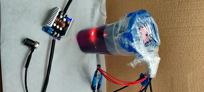
If anyone is interested, I can donate the board. I have fully wired my test board and will send you the close-ups of the wiring since I shrink-wrapped the leads so you know which lead is what.

I will mail the wired board in the picture at my own expense (including overseas) to anyone willing to spend time working on it to implement Simple FOC. If anyone is interested please let me know. The only condition is the person will work on FOC development and post the code and not something else.

I will also send you instructions on liquid cooling the board at home which is very safe and will not pollute (you can achieve food-safe passive liquid cooling for development at home cheaply).

The board thingy outside the cooling jar on the pic is a buck converter, this is not part of the setup. The dev board is dunked inside.

Not sure if this community board allows for DM/PM, hope it does. Iā€™ll need your address.

Cheers!

Edit: If anyone is interested in taking up my offer, I will also add a free brushless for testing. This library is useful and hope more people contribute.

1 Like

Hi @Valentine,

First of all I am experimenting with different FOC boards so I do not have time to experimentate with your setup, but I find it very nice of you that you are willing to donate your board :slight_smile:.

Also your liquid cool setup is very cool to see! :slight_smile:

May I ask what kind of issues you are experiencing with the board? Are you going to switch to a more high powered board that does not require these amount of cooling solutions?

Sure. Itā€™s about money and legal. I am doing this for work, not hobby. I design something a lot larger and my time is extremely expensive. The dev board price point is fantastic and I wanted something a lot simpler I can load and custom tweak for my work under MIT License. To many this licensing issue is meaningless but to me it is not. However, just that funny container of coolant cost 300. I can just buy fully developed and tested three commercial odrive dual boards or two VESC 6 MKV Speed Controller boards with all bells and whistles and use VESC to get what I want in one afternoon and call it a day and move on. Also, I hit some issues when trying current control and donā€™t have time spending in debugging STā€™s poor B-G431B documentation. In addition B-G431B hardware itself also has some legal and licensing issues. Coupled with heating and soldering and housing makes it nonviable. Spending time soldering at home and designing a custom liquid cooling is a non starter at that point.

My current line of action is to acquire a couple O-Drive and VESC boards to POC my design and will revisit B-G431B later. Backup is I design my own board from scratch with my hardware guy and manufacture in China.

Edit: If anyone is interested in taking up my offer, I will also add a free brushless for testing. This library is useful and hope more people contribute.

A ROS implementation is possible and it is working. The only thing that I changed in the Arduino sketch was this.

#define ROSMASTER_RX                        PB4     // UART2-RX
#define ROSMASTER_TX                        PB3    //  UART2-TX
#include "HardwareSerial.h"
HardwareSerial hserial(ROSMASTER_RX, ROSMASTER_TX);

// This will overwrite the current Serial1 serial port and will x use hserial port.
#define Serial1 hserial

// This define statement should be defined before including ros.h
#define USE_STM32_HW_SERIAL

The project is a series elastic actuator for a robot arm.

4 Likes

And some of the components, like the FETs, are not normally orderableā€¦ :frowning: but its still a nice reference design.
I think for SimpleFOC experimentation it is not the best choice because of the lack of easily usable IO. Its not easy to interface with sensors. etcā€¦

Correct. I donā€™t want to turn it into bashing the board, this is simply the wrong tool for my job. I can repurpose the PWM, and TX/RX and if I run sensor-less, the three hall sensors. Thatā€™s butchering. I wanted to add custom logic with external sensors. Plus as you mentioned, if you add up the BOM for the board, it greatly exceeds the $18 I paid, so if you carefully read the licensing this is an evaluation carrot before someone orders a 10,000 batch at five times the price. At which point we enter the realm of GPLā€™ed VESC 6 MKV. Which itself has issues but thatā€™s tangential. Very educational though.

BTW has anyone tried running SimpleFOC on the dozens of VESC compatible Chinese boards floating around on Amazon? I ordered one to evaluate, but just curious.

Thanks for the insights by the way. Very interesting to read it more from a work - instead of hobby perspective!

I know that @Owen_Williams got SimpleFOC running on VESC. Maybe the following thread is interesting for you: VESC Support - 1kW of Power! - SimpleFOC Community

I will look into this, thank you. Good pointer.

I received my B-G431B boards and gave it a first try, here my findings:

  • Setting it up on PlatformIO was working nicely with the instructions by Wittecactus, of course it will get easier once stm32duino 2.0 makes it into PlatformIO, until then the instructions are great!
  • I could not program the board through PlatformIO with stlink directly, I had to manually install OpenOCD 0.11.0 and make a custom .cfg file for the G431. I can share instructions and the config file if there is any interest, just let me know
  • My sensors have not arrived yet, I connected a 2450kV, 6 polepair motor and tested velocity_openloop on a 3s LiPo. I can turn the motor and command it through commander on the USB port on the daughterboard. But the motor and FETā€™s get super hot very quick and I am affraid to burn the board. Any advice what I could do to avoid it (without sensor for the moment). I share my current code below.

Thank you!

#include <Arduino.h>
#include "SimpleFOC.h"

//Motor and driver instance
BLDCMotor motor = BLDCMotor(6); 
BLDCDriver6PWM driver = BLDCDriver6PWM(PHASE_UH, PHASE_UL, PHASE_VH, PHASE_VL, PHASE_WH, PHASE_WL);`

// Commander instance
Commander command = Commander(Serial);

void doTarget(char* cmd) { command.scalar(&motor.target, cmd); }

void setup() {

    pinMode(LED_BUILTIN, OUTPUT);
    Serial.begin(115200);

    //Driver initialization
    driver.voltage_power_supply = 12;
    driver.init();

    //Limiting motor movements
    //motor.phase_resistance = 3.52 // [Ohm]
    //motor.current_limit = 2;   // [Amps] - if phase resistance defined
    motor.voltage_limit = 1;   // [V] - if phase resistance not defined
    //motor.velocity_limit = 5; // [rad/s] cca 50rpm
    //motor.voltage_limit = 1;

    //Control loop setup
    motor.controller = MotionControlType::velocity_openloop;

    //Init motor
    motor.linkDriver(&driver);
    motor.useMonitoring(Serial);
    motor.init();

    // add target command T
    command.add('T', doTarget, "target");
    command.add('t', doTarget, "target");

    Serial.println("Motor ready!");
    Serial.println("Set target velocity [rad/s]");

    delay(1000);
}

void loop() {

    //Motor loop, as quick as possible
    motor.move();

    //User communication
    command.run();

    //Monitoring
    //motor.monitor();
}

I suspect your phase resistance is a lot lower than 3.52 ohms. Probably more like 0.1 ohms.

I suspect itā€™ll run a lot cooler at 20 rad/s as bemf will reduce current. Have you tried a voltage_limit of 0.5 or lower?

Youā€™ll notice itā€™ll be a lot cooler if you can get closed loop working.

I had a look at the gerber files from ST. Im not surprised you had to put liquid cooling on it @Valentine.

It is a pity, since those mosfets can handle much more.

quote: * Output peak motor current (maximum peak current tested with propeller to have an air-forced cooling): 40 A.

I guess if one design with propeller cooling in mind, then thermal management is a different story.

Indeed Owen,

going down to 0.5 is working ok in openloop with this motor (FETā€™s just barely warm), but it brings me to another question: I think I understand that velocity_openloop is just calculating the desired angle over time, and puts the voltage (voltage_limit) to the phases according the desired angle (same as angle_openloop but with changing angle). Is it possible with this library, to have something like a voltage_openloop control, where we could target the motor to a certain voltage (or a certain pwm duty cycle), and the control is commutating the phases as quick as the motor ā€œnaturallyā€ wants to go? It would require detection of bemf zerocrossing tough, as kind of a sensor.

I love the library honestly, but then people could start using it in sensorless projects as well (there may be plenty out there). I was reading the docs and think it is not in yet, maybe it is not the goal of this lib even, but it would be very nice.

btw: any quick tip how to make the motor sound at a cerain frequency?

Regards
Christian