Hi, I have been working on a 3D printed BLDC outrunner motor. It has 20 poles and 18 slots. I know that it does work because I was able to hook it up to an RC ESC and it worked. I am hoping to use an Arduino UNO as a controller and an L298N as a driver for testing the motor. For sensors, I have hallsensors I know I need 3 spread out evenly. But I don’t know if they need to be put in with the stator or if I should put them on the inside of the case reading the rotor. I also don’t know how I would properly set them up with the Arduino. If you have any thought on what I’m doing wrong or what I can do better comments would be greatly appreciated.
Thank you for reading.


3 Likes
Welcome @purple!
20 poles means you have a 10 pole_pair motor - this value is passed to both BLDCMotor and HallSensor constructor.
The purpose of the hall sensors is to determine the 6 electrical sectors of 1 electrical rotation. As you have 10 pole_pairs there will be 10 electrical rotations for each shaft rotation. This will give you 6x10 hall transitions per shaft rotation i.e. a transition every 6 degrees. Your job is to ensure that you get a transition evenly every 6 degrees! You could either do this empirically (with an oscilloscope making adjustments in hall placement) or try to work it out through a bit of maths and a bit of luck.
Hall sequence will be something like this:
H1  H2  H3
-----------
 1   0   0
 1   1   0
 0   1   0
 0   1   1
 0   0   1
 1   0   0
If you think of the 1s as being a north pole and the 0s being a southpole then you can almost see a pole pair (north and south magnet) moving across the hall sensors in the table above!
I might have got the maths wrong but if H1 is at zero then H2 can be placed at 12 degrees (or 12 + (n 36)) and H3 at 24 degrees (or 24 + n36)) where you might choose n > 0 if you wanted to space out your halls a bit.
I’ve never tried to place halls, so would be interested to hear how you get on.
These halls will need pullup resistors otherwise the voltage will only vary between 0V and ~0.2V. I’ve used a pullup of 1 or 2K in the past but this is lower than some people recommend.
The hallsensor example might be a good place to start:
You might need to use a software interrupt for the third hall as I think uno only supports two hardware interrupts.
1 Like
thank you so much for helping me 
1 Like
Awesome project! I’d love to see it spinning with FOC!
I couldn’t add anything to what Owen had to say about Hall sensors, except that they’re better suited for fast-spinning applications, because of the 6° accuracy.
Have you looked at using a magnetic encoder IC? Something like an MA730 or AS5048A will be far more accurate for speeds under 10000RPM, and could be simpler to implement? Typically the motor only has to include a small magnet at its axis, and the sensor is mounted externally.
I think that I will move to use magnetic encoders but I do have some questions. Do I have to worry about the bearing screwing it up because I’m hoping to place it in the middle of it.
Also, where should I buy the encoder from and where should I buy the magnet from.
thank you for helping me out

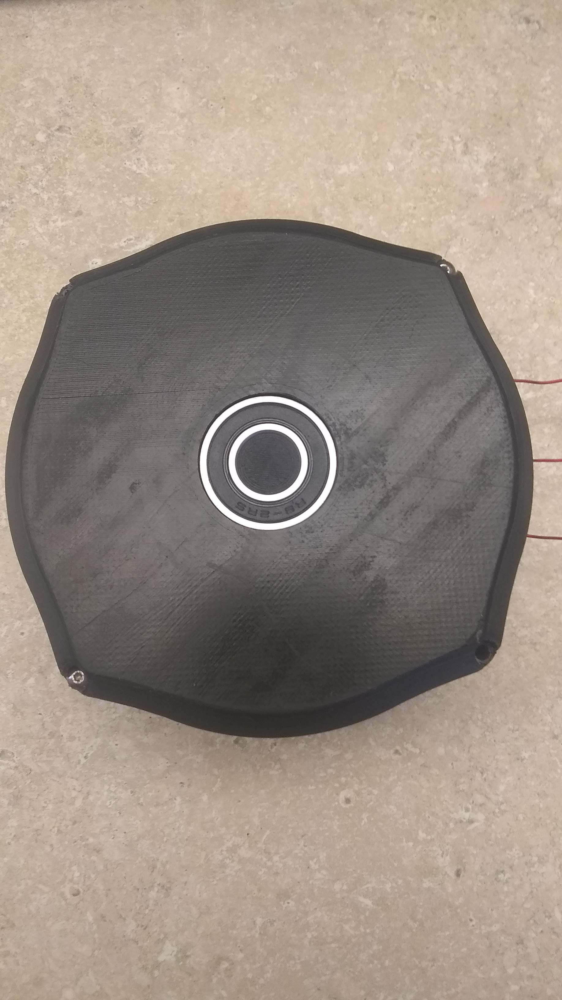
I think that last photo is showing the stator side. The inside of the bearing will be moving with the rotor. Is that a skateboard bearing (22mm outer, 8mm inner). So you’ll have a shaft going through this? I’d glue or attach magnet to end of shaft and then build a shim to hold the magnetic sensor a few mm away from magnet. Probably need some new holes in stator to attach this securely.
Some sensors come with a magnet (as5147?), others do not (ma730). You can pick up a 10x diametric magnet from ebay for £3 e.g.
Hi @purple,
In your case, if star winding, you have to put the Hall1 at 9° from middle of the first slot (phase A), and then at 12° for the followings.
You can also put the Hall1 after the first slot (phase A) between slots and then Hall3 on 6 slots after, and the Hall2 at 6 slots after for a 60° commutation.
Hey - magnets are available all over the place, and are cheap - amazon, eBay, AliExpress will all deliver. Just make double-sure they really are diametrically magnetised, some sellers are a bit vague or unreliable in their descriptions.
6-8mm is a good size for most of the sensors, with 2.5 or 3mm thickness.
For the encoders, be careful on AliExpress or eBay - many of the offerings only have their PWM lines soldered, and you are faced with a very difficult soldering job if you want to use SPI.
If you don’t mind the size, these will work well:
https://ams.com/as5048aadapterboard
https://ams.com/as5048amotorboard
They’re available direct, or also from Mouser, DigiKey etc… Note that these boards already come with the right kind of magnet.
@purple,
Another thing, if your stator is not made of steel lamellas (for the currents of Foucault), your brushless will not work (magnetic circuit).
Even with AS5048, MA730, as5047, Hall sensors,…
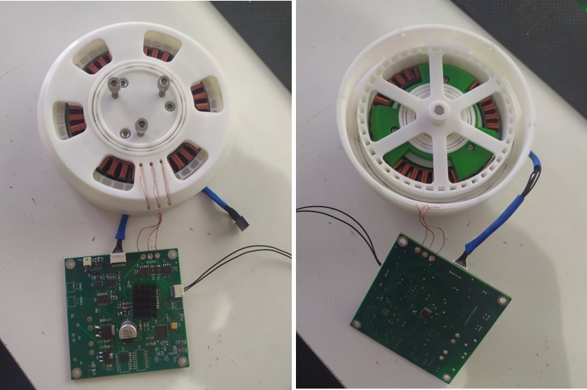
I was wondering about that, since it is a bit unclear from the pictures… what are the windings “wound around”? Is there a ferromagnetic core around which the windings are turned?
It is possible to print with metal-containing filaments… is this a technique you’re using?
The stator is not made out of Electrical steel but it will work but with less torque. I have put steel inside of the coils. for printing ferromagnetic PLA it doesn’t seem worth it because 1Kg costs 70 dollars so much more than what I’m going to pay. along with that winding by hand is a pain to do on a real coil. It’s much easier to wind one-third of it at a time on a jig. So if you need to make a new stator you can just take out the coils.

2 Likes
I’m fascinated!
It will be so cool if this works well.
I think it is particularily interesting in combination with 3D printing mechanical designs for things like linkages and hub-wheels, where the motor as a separate unit with housing and its coupling to the 3D printed parts take a significant amount of space. By being able to put rotor and stator directly into the printed parts, you only need to add bearings, and can achieve far more compact designs.
Very cool projekt!
Im sure you have seen the 3D printed BLDC on youtube?

For a outrunner to have any real efficiency, the windings must have a core. Like you mention yourself, the design is not optimal. It would be awesome to integrate a laminated core into your design. I have tried to reach out to this company here : List 1--Outer Stator - Drone Motors Manufacturer
Particularly the 15cm dia. nr. 86 (12slot) is interesting. I would not mind doing like 127 turns per coil. I’m not sure i can do it as well as a machine though, have not tried. That crazy-motor company has a coil winding machine…
No reply yet.
Here is another company. Maybe they will answer 

That is a pretty cool 3D design. But what kind of torque can it withstand ?
If you had a laminate (metal core) stator and a strong 3D printed rotor, maybe carbon fiber re-enforced filament, naturally it would be more heavy, but the forces would not scatter the plastic.
Ah here is the test statistics: below 1 Nm
Hey purple one
I watched this and thought about your project. It is a bit of work to set up, and you need the right tools. Vacuum chamber for degassing, making of mold. If you don’t want to see the soldering of windings skip to approx. mid vid. https://youtu.be/ZuTsvKQVkcw
If one was to reinforce the stator with carbon fiber compared to glass fiber it would have a higher torque rating, IMO.
There is no iron core in his design, but I don’t se why you couldn’t place some iron in the center of the coils.
This dude uses iron powder mixed with epoxy in a 3d printed mold. https://youtu.be/ZmzD1c7D214
10 € for a kilo iron powder, that’s not too expensive. https://www.laboratoriumdiscounter.nl/en/iron-powder-pure.html?gclid=CjwKCAjw7J6EBhBDEiwA5UUM2tPuUX8WjMcSOPbCUDJyLoAcpASSMAWZRnJltNECrpoY-hA9O1nnuhoCaOEQAvD_BwE
I would probably paint it with some paint for brake calibers.
Hi!
I’m working in a similar proyect (a 3D printed blcd with a planetary gearbox) and I want to use an arduino/simplefoc to control it. Have you been able to control yours?
I have been doing this myself for a few months. It is the design of a robotic actuator for a quadruped.
First, I discarded the idea of not using a core with electrical steel, since the torque was going to be much much lower. In my case I have used a hybrid solution.
The core is purchased from aliexpress, size 8110.
I rewind it with the following configuration (ending in Wye for more torque). I managed to put 36 turns with 0.35mm enameled copper wire.

It was meticulous work, but I think the result was very satisfactory 

The design of the actuator is based on the size of the stator, here I attach some diagrams of the 3D design. It has a 1:3.2 planetary reducer inside the metal core itself. The magnets are embedded under pressure.
The overall size is 113mm in diameter and 35mm thick.

The bearings are also self-designed and 3D printed due to commercial size, weight and price restrictions.
What I do is print half the bearing, pause the print, put the steel balls (4mm) and continue the print.
The bearings are performing well, but the tolerances are very tight and they sound too high at high speed. I am looking at the possibility of using other materials (nylon) with a lower coefficient of friction.
I have configured everything to work with the L6234 driver on a custom PCB, therefore I have a theoretical limit of 5A.
The tests that I have carried out are quite good, at 18.3V have a consumption of 3.5A, with a maximum torque (without reducer) of 1.1N·m with a stable maximum speed of 46rad/s.
With the planetary gearbox I get around 3.5N·m.
The total weight of the actuator mounted with the PCB is around 360g. Possibly you can reduce it a few more grams.
I have not yet implemented the Halbach Array, so I have been able to investigate it would gain around 10-15% more efficiency. I have also pending to reduce the gap between the stator and the magnets (currently it is 1.3mm), for more efficiency.
Currently the biggest problem I have is the temperature when I start applying torque and amps.
For the first prototype I printed everything with PLA, and you already know what happens when the coils are heated to 60 / 70ºC
Attached photos of the 3D printed actuator.
Now that I know that the design and the implementation is functional, I am investigating to print in nylon + CF or in polycarbonate with a theoretical maximum temperature of 120 / 150ºC.
7 Likes
This is awesome! I think you should look intro drill gearboxes to find a nice and cheap replacement of the plastic gears.
1 Like